158 Results
View Results:
Sort by:

When it comes to wind loads on building type structures as per ASCE 7, numerous resources can be found to supplement design standards and aid engineers with this lateral load application. However, engineers may find it more difficult to find similar resources for wind loading on non-building type structures. This article will examine the steps to calculate and apply wind loads as per ASCE 7-22 on a circular reinforced concrete tank with a dome roof.

When it comes to wind loads on building type structures as per ASCE 7, numerous resources can be found to supplement design standards and aid engineers with this lateral load application. However, engineers may find it more difficult to find similar resources for wind loading on non-building type structures. This article will examine the steps to calculate and apply wind loads as per ASCE 7-16 on a circular reinforced concrete tank with a dome roof.

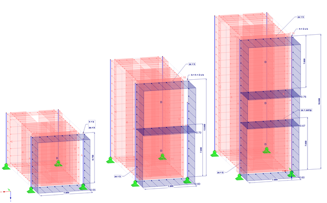
The wind load of rectangular rounded structural components is a complex matter. The equivalent forces from wind load depend on the strength of the circulating wind load and the component geometry.

In Germany, DIN EN 1991-1-4 with the National Annex DIN EN 1991-1-4/NA regulates the wind loads. The standard applies to civil engineering works up to an altitude of 300 m.

The Eurocode for DIN EN 1991‑1‑4:2010‑12 describes wind loads acting on structural systems.

Wind blowing parallel to the surfaces of a structure can generate friction forces on these surfaces. This effect is important mainly for very large structures.
The wind loads are regulated according to Eurocode 1 - Actions on Structures - Part 1-4: General actions - Wind loads. The nationally determined parameters of a respective country can be found in the National Annexes.

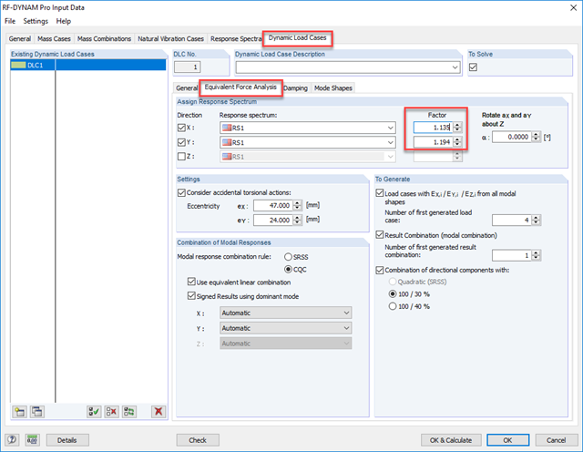
Both the determination of natural vibrations and the response spectrum analysis are always performed on a linear system. If nonlinearities exist in the system, they are linearized and thus not taken into account. They are caused by, for example, tension members, nonlinear supports, or nonlinear hinges. This article shows how you can handle them in a dynamic analysis.

For foundation design, it is necessary to define the relevant loads for the respective design situations (STR, GEO, UPL, EQU).

RF‑CONCRETE Surfaces for RFEM 5 allows you to use averaged internal forces for design of concrete surfaces.

Using the RF-TIMBER AWC module, timber column design is possible according to the 2018 NDS standard ASD method. Accurately calculating timber member compressive capacity and adjustment factors is important for safety considerations and design. The following article will verify the maximum critical buckling in RF-TIMBER AWC using step-by-step analytical equations as per the NDS 2018 standard including the compressive adjustment factors, adjusted compressive design value, and final design ratio.

In this article, the adequacy of a 2x4 dimension lumber subject to combined biaxial bending and axial compression is verified using the RF-/TIMBER AWC add-on module. The beam-column properties and loading are based on example E1.8 of AWC Structural Wood Design Examples 2015/2018.

Wind direction plays a crucial role in shaping the outcomes of Computational Fluid Dynamics (CFD) simulations and the structural design of buildings and infrastructures. It is a determining factor in assessing how wind forces interact with structures, influencing the distribution of wind pressures, and consequently, the structural responses. Understanding the impact of wind direction is essential for developing designs that can withstand varying wind forces, ensuring the safety and durability of structures. Simplified, the wind direction helps in fine-tuning CFD simulations and guiding structural design principles for optimal performance and resilience against wind-induced effects.

RF-PUNCH Pro performs punching shear design on concentrated load application locations (column connection, nodal support, and nodal load) as well as on wall ends and wall corners.

Windbreak structures are special types of fabric structures which protect the environment from harmful chemical particles, abate wind erosion, and help to maintain valuable sources. RFEM and RWIND are used for wind-structure analysis as one-way fluid-structure interaction (FSI).
This article demonstrates how to structural design windbreak structures using RFEM and RWIND.

- 001530
- Modeling | Loading
- RFEM 5
-
- RSTAB 8
- RX-TIMBER Glued-Laminated Beam 2
- RX-TIMBER Roof 2
- RX-TIMBER Continuous Beam 2
- RX-TIMBER Purlin 2
- RX-TIMBER Frame 2
- RX-TIMBER Column 2
- RX-TIMBER Brace 2
- Buildings
- Concrete Structures
- Steel Structures
- Timber Structures
- Process Manufacturing Plants
- Temporary Structures
- Structural Analysis & Design
- Eurocode 1
- Eurocode 0
In Germany, DIN EN 1991-1-3 with National Annex DIN EN 1991-1-3/NA regulates snow loads. The standard applies to civil engineering works at altitudes of up to 1,500 m above sea level.

In the existing standard, there were no regulations for the distribution of snow loads for elevated solar thermal and photovoltaic systems on roofs. Only distribution of the loads was advised. It was only with the National Annex DIN EN 1991-1-3/NA: 2019-04 that specific regulations were made for this.
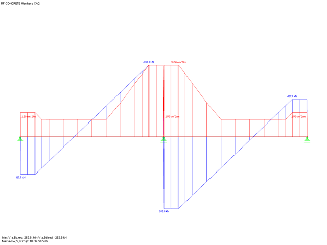
When performing shear force design in RF-CONCRETE Members and CONCRETE, you can reduce the acting shear force Vz according to EN 1992-1-1. The following article describes the reduction of the concentrated loads close to the support and the shear force design at the distance d from the support face for a uniform load.

In RF-/FOUNDATION Pro, you can also consider the concrete cover for the foundation according to EN 1992-1-1.

In RF-/FOUNDATION Pro, the foundation design requires the definition of the corresponding loading (load cases, load combinations, or result combinations) for different design situations (STR, GEO, UPL, or EQU).

The secondary reinforcement according to DIN EN 1992-1-1 9.2.1 is used to ensure the desired structural behavior. It should avoid failure without prior notification. The minimum reinforcement has to be arranged independently of the size of the actual loading.

If a rib is part of a nonlinear design or is rigidly connected to following walls, a surface should be used for the modeling instead of a member. So that the rib can still be designed as a member, a result member with the correct eccentricity is required, which transforms the surface internal forces into member internal forces.

In RFEM and RSTAB, different graphical representations of the foundation dimensions are available.

Using RF-CONCRETE Members, concrete column design is possible according to ACI 318-14. Accurately designing concrete column shear and longitudinal reinforcement is important for safety considerations. The following article will confirm the reinforcement design in RF-CONCRETE Members using step-by-step analytical equations as per the ACI 318-14 standard, including required longitudinal steel reinforcement, gross cross-sectional area, and tie size/spacing.

The size of the computational domain (wind tunnel size) is an important aspect of wind simulation that has a significant impact on the accuracy as well as the cost of CFD simulations.
With RF-PUNCH Pro, the punching shear design can be performed according to 6.4, EN 1992-1-1. In the following example, the design according to DIN EN 1992-1-1 will be presented first with automatic design of the inner and outer perimeters and then on the basis of the inner perimeters defined by the user on a simple example.

In RF-PUNCH Pro, enlarged column heads can be arranged at point-supported punching shear points, thus increasing the shear force resistance of a reinforced concrete floor. In the following article, we will show the punching shear design with the optional application of an enlarged column head.

The punching shear design, in line with EN 1992-1-1, should be performed for slabs with a concentrated load or reaction. The node where the design of punching shear resistance is performed (that is, where there is a punching problem) is called a node of punching shear. The concentrated load at these nodes can be introduced by columns, concentrated force, or nodal supports. The end of the linear load introduction on slabs is also regarded as a concentrated load and therefore, the shear resistance at wall ends, wall corners, and ends or corners of line loads and line supports should be controlled as well.

For structural components consisting of slabs, it is necessary to perform shear design on the locations with concentrated load introduction, applying the punching shear design rules according to Sect. 6.4 of EN 1992‑1‑1 [1]. The concentrated load introduction is present on the individual locations; for example, by columns, concentrated load, or nodal supports. In addition, the end of linear load introduction on slabs is also regarded as concentrated load introduction. For example, this includes wall ends, wall corners, and ends or corners of line loads and line supports. You can perform the punching shear design for floor slabs or foundations, considering the existing available plate topology about the designed node of punching shear. The punching shear design according to EN 1992‑1‑1 checks that the acting shear force vEd does not exceed the resistance vRd.
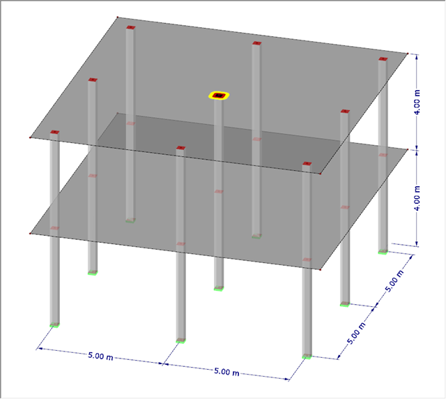
As gravity loads act on a structure, lateral displacement occurs. In turn, a secondary overturning moment is generated as the gravity load continues to act on the elements in the laterally displaced position. This effect is also known as "P-Delta (Δ)". Sec. 12.9.1.6 of the ASCE 7-16 Standard and the NBC 2015 Commentary specify when P-Delta effects should be considered during a modal response spectrum analysis.