57 Results
View Results:
Sort by:

This article presents the basic concepts in structural dynamics and their role in the seismic design of structures. Great emphasis is given to explaining the technical aspects in an understandable way, so that readers without deep technical knowledge can gain an insight into the subject.

The modal relevance factor is a result of the linear stability analysis and qualitatively describes the degree of participation of individual members in a specific mode shape.

Custom sections are often required in cold-formed steel design. In RFEM 6, the custom section can be created using one of the “Thin-Walled” sections available in the library. For other sections that do not meet any of the 14 available cold-formed shapes, the sections can be created and imported from the standalone program, RSECTION. For general information on AISI steel design in RFEM 6, refer to the Knowledge Base article provided at the end of the page.

Surfaces in building models can be of many different sizes and shapes. All surfaces can be considered in RFEM 6 because the program allows to define different materials and thicknesses as well as surfaces with different stiffness and geometry types. This article focuses on four of these surface types: rotated, trimmed, without thickness, and load transfer.

The “Modal Analysis” add-on in RFEM 6 allows you to perform modal analysis of structural systems, thus determining natural vibration values such as natural frequencies, mode shapes, modal masses, and effective modal mass factors. These results can be used for vibration design, as well as for further dynamic analyses (for example, loading by a response spectrum).

This article will show you a practical example of how to determine critical load factors and corresponding mode shapes in RFEM 6.

Modal analysis is the starting point for the dynamic analysis of structural systems. You can use it to determine natural vibration values such as natural frequencies, mode shapes, modal masses, and effective modal mass factors. This outcome can be used for vibration design, and it can be used for further dynamic analyses (for example, loading by a response spectrum).

Imperfections in construction engineering are associated with production-related deviation of structural components from their ideal shape. They are often used in a calculation to determine the equilibrium of forces for structural components on a deformed system.

RFEM 6 includes the Form-Finding add-on to determine the equilibrium shapes of surface models subjected to tension and members subjected to axial forces. Activate this add-on in the model's Base Data and use it to find the geometric position in which the prestress of lightweight structures is in equilibrium with the existing boundary conditions.

The number of National Annexes for Eurocode 2 with regard to the design of reinforced concrete cross-sections has been extended since SHAPE-MASSIVE 6.54. Therefore, the following NAs of EN 1992-1-1:2004 + AC:2010 are available:

In addition to the geometry and shape of a flat roof, you can also take into account the formation of an eaves area when generating the loading.
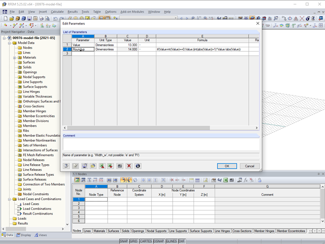
In RFEM, RSTAB, and SHAPE-THIN, you can use formulas to determine a numerical value.
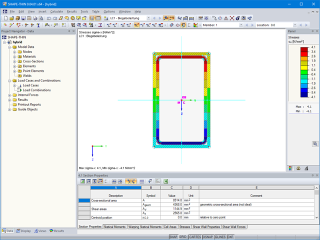
The material allocation for hybrid SHAPE‑THIN cross‑sections can be selected easily in RFEM and RSTAB. The prerequisite for this is the allocation of different materials to the cross‑section elements in SHAPE‑THIN.

The SHAPE‑THIN and SHAPE‑MASSIVE cross-section programs are suitable for determining the cross-section properties of common thin-walled or thick-walled sections. These cross-section properties are also available for further analyses in RSTAB and RFEM.

With the SHAPE‑THIN cross‑section properties software, you can create any thin‑walled cross‑section and use it in RFEM or RSTAB as a member cross‑section. SHAPE‑THIN can give all relevant cross‑section values of any cross‑section for a design and stress analysis.

You can use the "Free Circular Load" option in RFEM to apply a partial uplift force to a cone‑shaped floor slab. It can be defined as linearly variable. The definition of center C and the outer boundary R can be specified easily, using the select function.
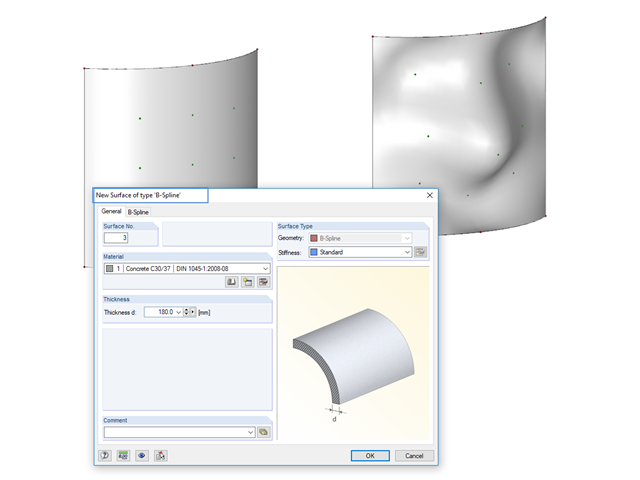
Instead of a quadrangular surface, you can use a B‑spline surface. The shape of this can be adjusted retrospectively, using the integrated help nodes. Depending on the necessary surface complexity, you can create a B‑spline surface with 3 × 3 or 4 × 4 help nodes.

In RFEM, RSTAB, and SHAPE-THIN, you can create user-defined print templates ("Printout Report Template") and printout headers ("Report Headers"). These templates can also be transferred to other computers and used there.
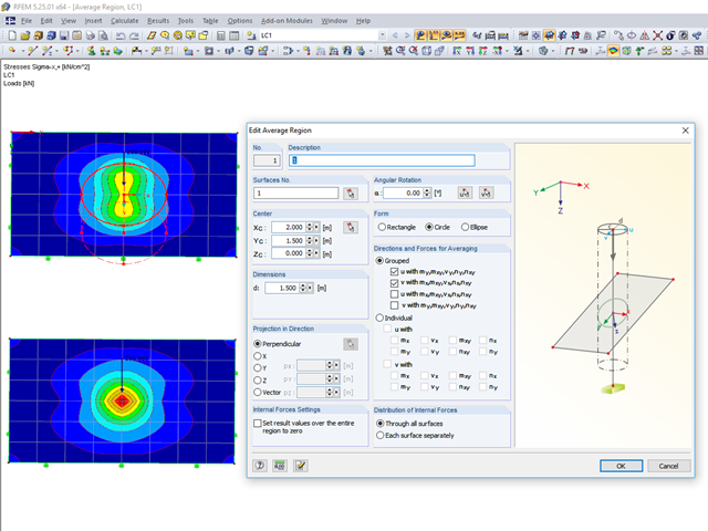
RFEM 5 provides the option to define a smoothing area in the "Results" → "New Average Region" menu. You can choose a rectangular, circular, or elliptical shape. With this tool you can, for example, "smooth" singularities due to nodal loads in a desired averaged region.
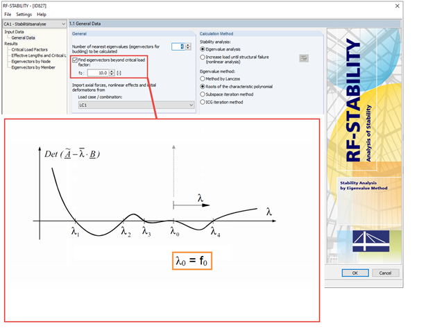
The function, which is also known as shifting, allows you to calculate critical load factors beyond a user‑defined initial value. Determination of the critical load factors is usually done from the smallest to the greatest critical load factor.
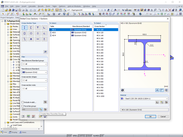
The "Filter" option in the cross‑section library allows you to show only cross‑sections of certain standards, shapes, or types. In the same window, you can also select the material.
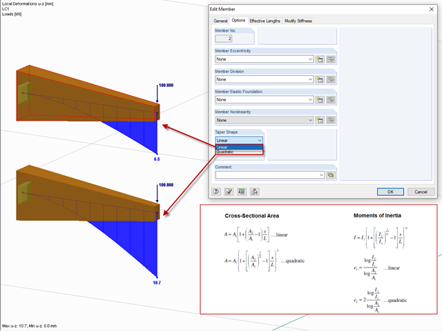
After right-clicking a member and selecting "Edit Member", you can find the "Taper Shape" option in the "Options" tab.
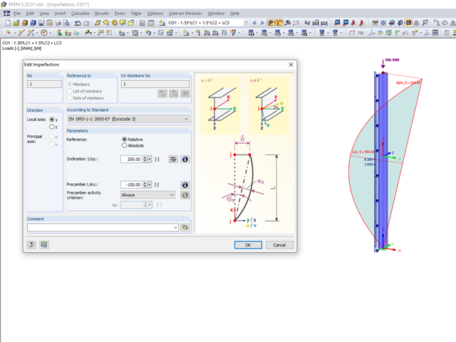
In the world of construction engineering, the word "imperfections" has a specific meaning. In general, it describes the incompleteness of a structure or the deviation of a structural component from an ideal shape caused by the production.
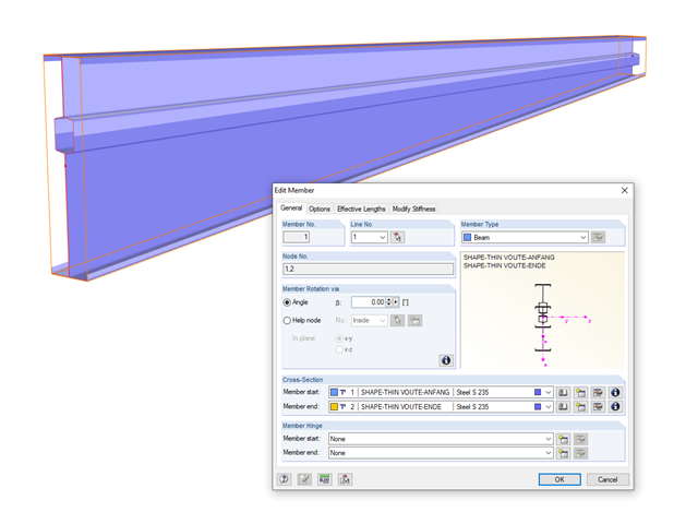
In RFEM and RSTAB, you can analyze members with a variable cross-section, which can also consist of freely defined SHAPE-THIN cross-sections. The cross-section properties are interpolated in order to determine the internal forces and deformations.
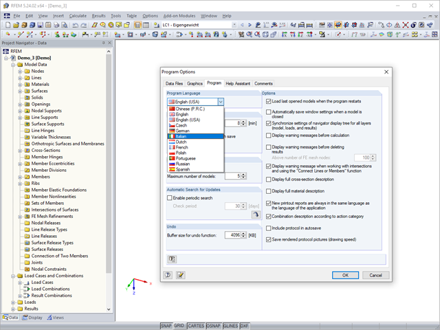
RFEM, RSTAB, and SHAPE-THIN are localized in eleven languages. All languages are available at no extra charge. The language of the program interface can be defined in the menu "Options" → "Program Options".
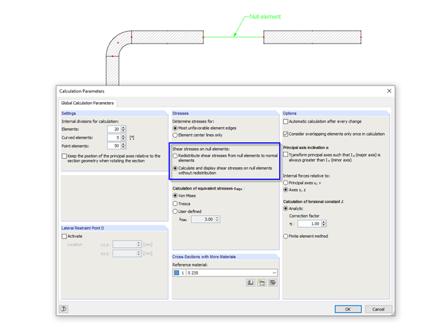
In cross‑sections created in SHAPE‑THIN, the openings, such as bolt holes, can be modeled by using the elements with zero thickness. The program provides two options for calculating shear stresses in the area of such null elements.

The elastic deformations of a structural component due to a load are based on Hooke's law, which describes a linear stress-strain relation. They are reversible: After the relief, the component returns to its original shape. However, plastic deformations lead to irreversible deformations. The plastic strains are usually considerably larger than the elastic deformations. For plastic stresses of ductile materials such as steel, yielding effects occur where the increase in deformation is accompanied by hardening. They lead to permanent deformations - and in extreme cases to the destruction of the structural component.

The design of cold-rolled steel products is defined in EN 1993-1-3. Typical cross-section shapes are channel, C, Z, top hat, and sigma sections. These are cold-rolled steel products made of thin-walled sheet metal that has been cold-formed by roll-forming or bending methods. When designing the ultimate limit states, it is also necessary to ensure that local transverse forces do not lead to compression, crippling of the web, or local buckling in the web of the sections. These effects can be caused by local transverse forces by the flange into the web, as well as by support forces at the supported points. Section 6.1.7 of EN 1993-1-3 specifies in detail how to determine the resistance of the web Rw,Rd under local transverse forces.

Utilize the RF-/STEEL Cold-Formed Sections module extension to perform ultimate limit state designs of cold-formed sections according to EN 1993-1-3 and EN 1993-1-5. In addition to the cold-formed cross-sections from the cross-section database, you can design general cross-sections from SHAPE-THIN.

A welded connection of an HEA cross-section under biaxial bending with axial force will be designed. The design of welds for the given internal forces according to the simplified method (DIN EN 1993-1-8, Clause 4.5.3.3) by means of SHAPE-THIN will be performed.