438 Wyniki
Wyświetl wyniki:
Sortuj według:

Niniejszy artykuł dotyczy długotrwałego ugięcia konstrukcji betonowych zgodnie z ACI 318 i CSA A23.3.

Analiza wyboczenia giętnego jest połączeniem analizy stateczności i stanu granicznego nośności, stosowana w konstrukcjach stalowych od setek lat. Punktem wyjścia do rozważenia kwestii stateczności jest krytyczne obciążenie wyboczeniowe, ale dotychczas nie przeprowadzono obliczeń bez uwzględnienia imperfekcji. Jak dokładnie określane są te imperfekcje?

Podczas obliczania siły tnącej w programie Wymiarowanie betonu zbrojonego, działającą siłę tnącą Vz można zredukować zgodnie z EN 1992-1-1. Poniższy artykuł opisuje redukcję siły tnącej od obciążeń skupionych w pobliżu podpory oraz wymiarowanie sił tnących w odległości d od krawędzi podpory w przypadku obciążenia równomiernie rozłożonego.

Każdego dnia tysiące inżynierów konstrukcyjnych projektują elementy konstrukcyjne, korzystając z wzorów kontroli projektu, uwzględniających krytyczne obciążenie wyboczeniowe. Ale skąd wzięły się te starożytne wzory, które opracował ponad 200 lat temu i które stanowią podstawę wszystkich trzech koncepcji projektowania konstrukcji stalowych?

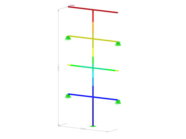
W tym artykule wyjaśniono różne metody dostępne w rozszerzeniu Analiza modalna, służące do określania liczby postaci własnych.

Dzięki rozszerzeniu Projektowanie konstrukcji stalowych możliwe jest projektowanie konstrukcji stalowych zgodnie z normą AISC 360-22. W poniższym artykule porównano wyniki obliczeń zwichrzenia zgodnie z rozdziałem F z analizą wartości własnych.
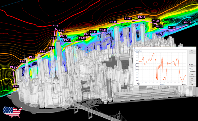
W inżynierii konstrukcyjnej przewidywanie wpływu turbulentnego przepływu wiatru na konstrukcje ma kluczowe znaczenie dla bezpieczeństwa i wydajności. Modelowanie turbulencji w Computational Fluid Dynamics (CFD) pomaga w symulacji tych interakcji. Inżynierowie muszą wybrać praktyczny model turbulencji, równoważąc wydajność, dokładność i możliwości zastosowania. Typowe modele to uśredniony Navier-Stokes (RANS), niestabilny uśredniony Navier-Stokes (URANS) oraz Delayed Detached Eddy Simulation (DDES). Program RANS jest niezawodnym i ekonomicznym rozwiązaniem w przypadku stałych przepływów, URANS rejestruje zależne od czasu zjawiska dla średnich niestateczności, a DDES, hybryda RANS i symulacji dużych wirów (LES), rozwiązuje złożone struktury turbulentne. Zrozumienie mocnych stron i ograniczeń każdego modelu pomoże inżynierom wybrać najlepsze podejście do swoich potrzeb.
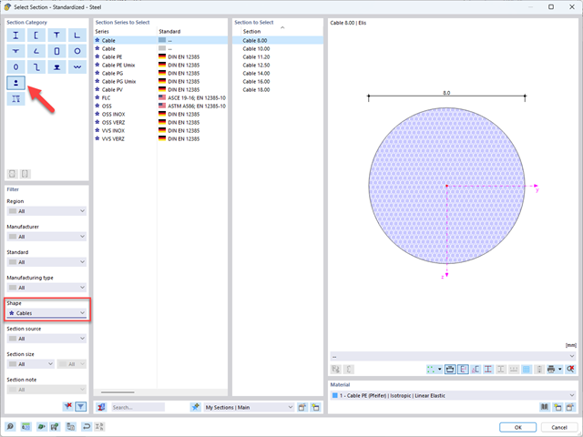
Z tego artykułu dowiesz się, jak modelować i wymiarować konstrukcje kablowe w programach RFEM 6 i RSTAB 9.
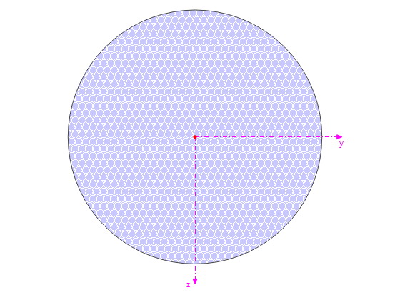
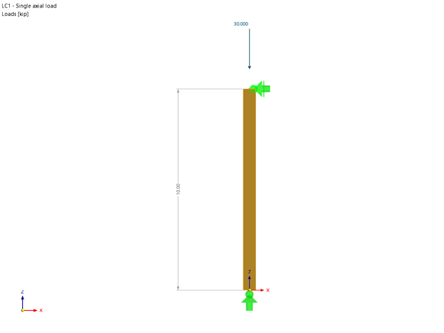
Ten artykuł opisuje i wyjaśnia wpływ sztywności na zginanie kabli na ich siły wewnętrzne. Z tego artykułu dowiesz się również, jak zredukować ten wpływ.

W artykule przedstawiono podstawowe pojęcia z zakresu dynamiki konstrukcji i ich roli w projektowaniu konstrukcji sejsmicznych. Duży nacisk kładzie się na wyjaśnienie aspektów technicznych w zrozumiały sposób, aby tematyka była zrozumiała dla czytelników bez dużej wiedzy technicznej.

Wyboczenie giętno-skrętne (LTB) jest zjawiskiem, które występuje, gdy belka lub element konstrukcyjny są zginane, a pas ściskany nie jest wystarczająco podparty bocznie. Prowadzi to do kombinacji przemieszczenia bocznego i skręcenia. Jest to decydujący czynnik przy wymiarowaniu elementów konstrukcyjnych, zwłaszcza smukłych belek i dźwigarów.
Rozszerzenie Wymiarowanie drewna umożliwia wymiarowanie słupów drewnianych zgodnie ze standardową metodą ASD 2018 NDS. Dokładne wyznaczenie nośności na ściskanie oraz współczynników redukcyjnych dla prętów drewnianych jest konieczne dla bezpieczeństwa konstrukcji. Poniższy artykuł weryfikuje maksymalną wytrzymałość na wyboczenie krytyczną obliczoną w module rozszerzeniowym Wymiarowanie drewna przy użyciu równań analitycznych krok po kroku zgodnie z normą NDS 2018, w tym współczynników dostosowania przy ściskaniu, skorygowanej wartości obliczeniowej na ściskanie i końcowego stopnia wyboczenia.

Obliczenia ze względu na zmęczenie zgodnie z EN 1992-1-1 należy przeprowadzać w przypadku elementów konstrukcyjnych, które są poddane działaniu dużych zakresów naprężeń i/lub wielu zmianom obciążenia. W takim przypadku obliczenia dla betonu i zbrojenia są przeprowadzane osobno. Dostępne są dwie alternatywne metody obliczeniowe.
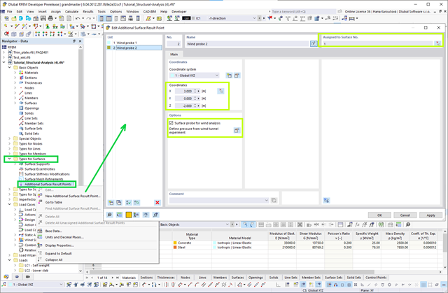
Jeśli dostępne są wyniki parcia powierzchniowego na budynek wywołane wiatrem, można je zastosować w modelu konstrukcyjnym w programie RFEM 6, przetworzonym przez RWIND 2 i wykorzystać jako obciążenia wiatrem do analizy statycznej w RFEM 6.
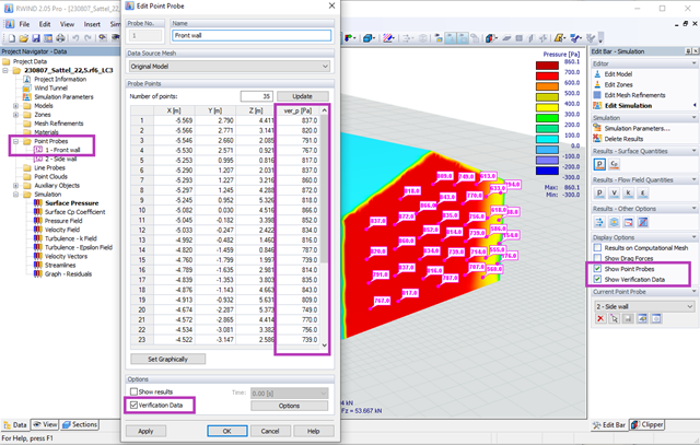
Za pomocą programów RWIND 2 i RFEM 6 można teraz obliczać obciążenia wiatrem na podstawie zmierzonego eksperymentalnie ciśnienia wiatru na powierzchnie. Zasadniczo dostępne są dwie metody interpolacji, umożliwiające rozłożenie ciśnienia mierzonego w izolowanych punktach na powierzchnie. Żądany rozkład ciśnienia można uzyskać za pomocą odpowiedniej metody i ustawień parametrów.

Obliczanie ramy momentowej zgodnie z AISC 341-16 jest teraz możliwe w rozszerzeniu Projektowanie konstrukcji stalowych dla programu RFEM 6. Wynik obliczeń sejsmicznych jest podzielony na dwie sekcje: wymagania dotyczące prętów i połączeń. W tym artykule omówiono wymaganą wytrzymałość połączenia. Przedstawiono przykładowe porównanie wyników pomiędzy RFEM a AISC Seismic Design Manual.
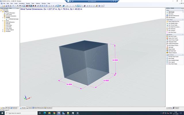
Stworzenie przykładu walidacyjnego dla obliczeniowej mechaniki płynów (CFD) jest kluczowym krokiem w zapewnieniu dokładności i wiarygodności wyników symulacji. This process involves comparing the outcomes of CFD simulations with experimental or analytical data from real-world scenarios. The objective is to establish that the CFD model can faithfully replicate the physical phenomena it is intended to simulate.
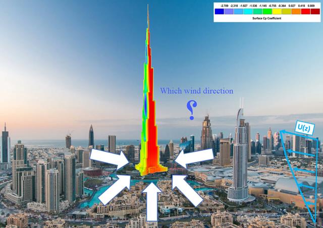
Kierunek wiatru odgrywa kluczową rolę w kształtowaniu wyników symulacji komputerowej mechaniki płynów (CFD) oraz w projektowaniu konstrukcyjnym budynków i infrastruktury. Jest to decydujący czynnik w ocenie interakcji sił wiatru z konstrukcjami, wpływających na rozkład ciśnienia wiatru, a w konsekwencji na reakcje konstrukcji.
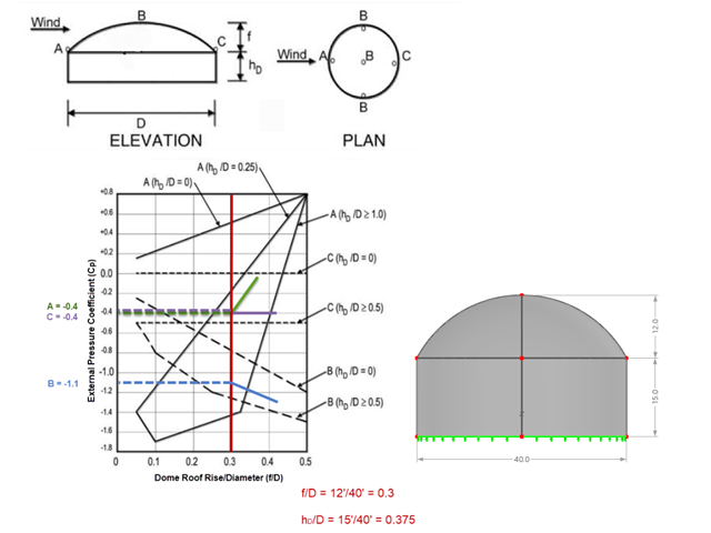
Jeśli chodzi o obciążenia wiatrem konstrukcje budowlane zgodnie z ASCE 7, można znaleźć wiele źródeł, które mogą uzupełnić normy projektowe i pomóc inżynierom w zastosowaniu obciążeń poprzecznych. Jednak inżynierom może być trudniej znaleźć podobne zasoby dla obciążeń wiatrem na konstrukcjach innych niż budynki. W tym artykule omówiono etapy obliczania i przykładania obciążeń wiatrem zgodnie z ASCE 7-22 na okrągłym zbiorniku żelbetowym z dachem w kształcie kopuły.
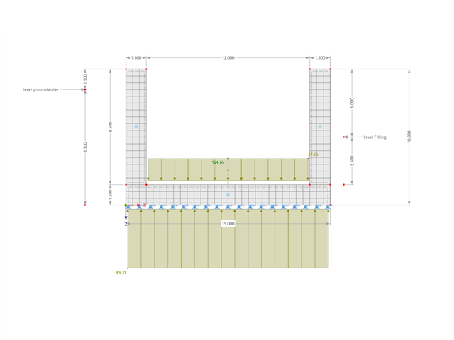
Ten przykład pokazuje, jak szybko określić w programie RFEM wyporność lub stan graniczny wyporności dla kontenera.
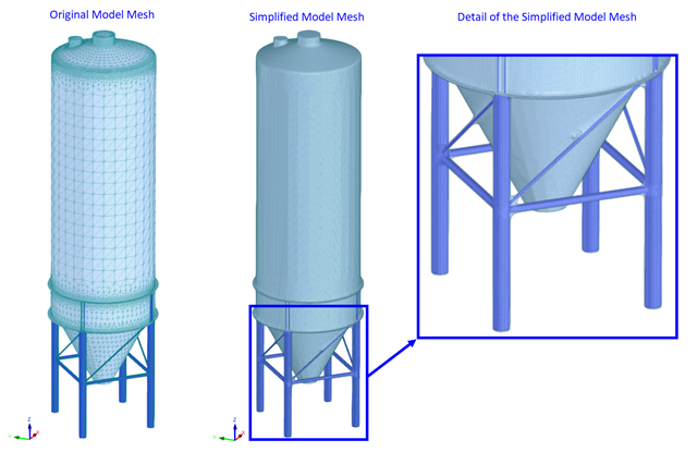
Obliczenia CFD są na ogół bardzo złożone. Dokładne obliczenia przepływu wiatru wokół skomplikowanych konstrukcji są bardzo czasochłonne i kosztowne. W wielu zastosowaniach inżynierskich wysoka dokładność nie jest wymagana, a nasz program CFD RWIND 2 pozwala w takich przypadkach uprościć model konstrukcji i znacznie zredukować koszty. W tym artykule odpowiedzi na niektóre pytania dotyczące uproszczenia.
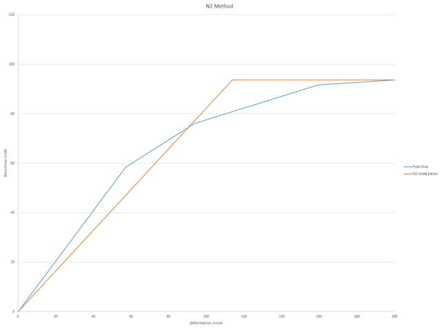
Aby można było przeprowadzić obliczenia push-over, należy zdefiniowaną krzywą nośności przekształcić do postaci uproszczonej. Tak zwana metoda N2 jest opisana w Eurokodzie EN 1998. Ten artykuł powinien pomóc w wyjaśnieniu, co oznacza bilinearyzacja zgodnie z metodą N2.
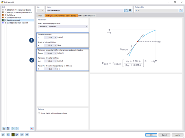
Rozszerzenie Analiza geotechniczna zapewnia programowi RFEM dodatkowe specyficzne modele materiałowe podłoża, które mogą odpowiednio odwzorować złożone zachowanie materiału podłoża. W tym artykule zaprezentujemy, w jaki sposób można określić zależną od naprężeń sztywność modeli materiałowych gruntu.

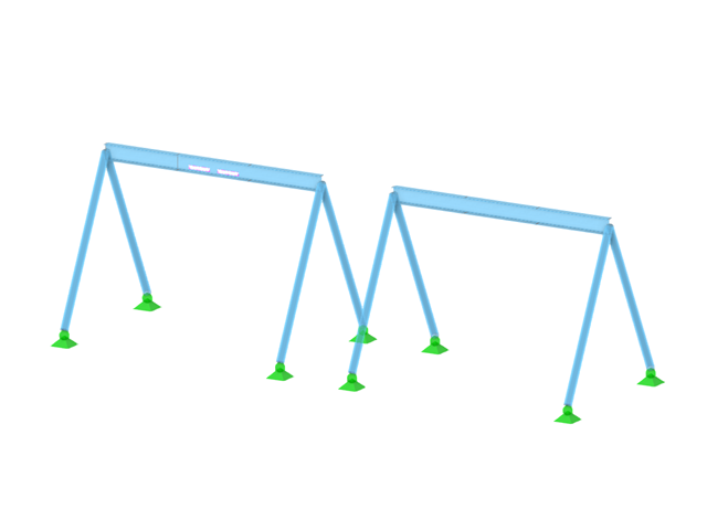
W tym artykule przedstawiono model połączenia zakładkowego płatwi ZL na dachu jednospadowym, obliczony w rozszerzeniu Połączenia stalowe i porównany z tabelą nośności podaną przez producenta.
Zgodność z przepisami budowlanymi, takimi jak Eurokod, jest niezbędna dla zapewnienia bezpieczeństwa, integralności konstrukcji i trwałości budynków i konstrukcji. Obliczeniowa mechanika płynów (CFD) odgrywa istotną rolę w tym procesie, symulując zachowanie płynów, optymalizując projekty i pomagając architektom i inżynierom w spełnieniu wymagań Eurokodu związanych z analizą obciążenia wiatrem, wentylacją naturalną, bezpieczeństwem pożarowym i efektywnością energetyczną. Integrując CFD z procesem projektowania, profesjonaliści mogą tworzyć bezpieczniejsze, wydajniejsze i zgodne z przepisami budynki, które spełniają najwyższe standardy konstrukcyjne i projektowe w Europie.
Analiza spektrum odpowiedzi jest jedną z najczęściej stosowanych metod obliczeniowych w przypadku obciążenia trzęsieniem ziemi. Metoda ta ma wiele zalet, a najważniejsza z nich to możliwość znacznego uproszczenia obliczeń. Skomplikowany charakter obciążenia jakim jest trzęsienie ziemi jest upraszczany do postaci, która umożliwia przeprowadzenie analizy o rozsądnym stopniu pracochłonności. Wadą metody jest natomiast to, że w wyniku tego uproszczenia traci się część informacji o obciążeniu. Sposobem na zniwelowanie tego ograniczenia może być zastosowanie równoważnej kombinacji liniowej podczas łączenia odpowiedzi modalnych. W poniższym artykule wyjaśniono to bardziej szczegółowo na konkretnym przykładzie.
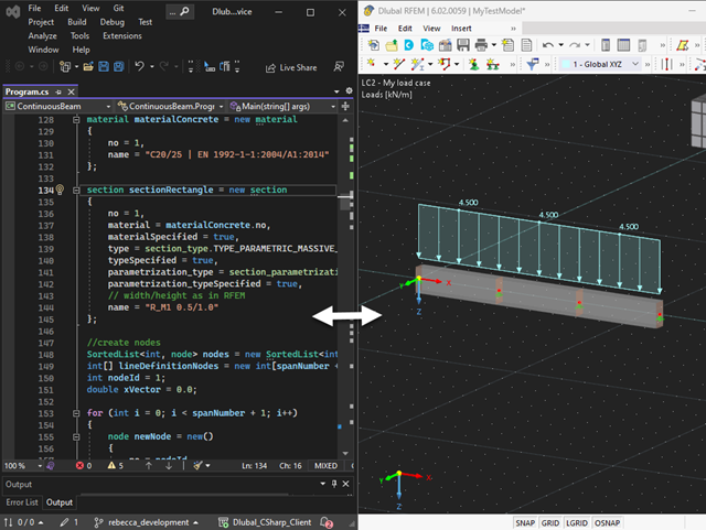
Nasza usługa sieciowa oferuje użytkownikom możliwość komunikacji z programami RFEM 6 i RSTAB 9 za pomocą różnych języków programowania. Funkcje wysokiego poziomu (HLF) firmy Dlubal umożliwiają rozszerzenie i uproszczenie funkcjonalności WebService. Zgodnie z RFEM 6 i RSTAB 9, korzystanie z naszego webservice sprawia, że praca inżyniera jest łatwiejsza i szybsza. Wypróbuj teraz! Ten samouczek pokazuje, jak korzystać z biblioteki C #na prostym przykładzie.
W wielu konstrukcjach szkieletowych zastosowanie prostego pręta nie jest już wystarczające. Często należy wziąć pod uwagę osłabienia przekroju lub otwory w belkach betonowych. Dla takich zastosowań dostępny jest typ pręta "Model powierzchniowy". Można go można zintegrować z modelem jak w przypadku każdego innego pręta i oferuje on wszystkie opcje modelu powierzchniowego. Ten artykuł techniczny pokazuje zastosowanie pręta typu Model powierzchniowy w istniejącym układzie konstrukcyjnym i opisuje integrację otworów pręta.
Modalny współczynnik istotności jest wynikiem analizy stateczności liniowej i opisuje jakościowo stopień udziału poszczególnych prętów w określonym kształcie drgań.
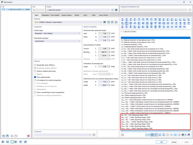
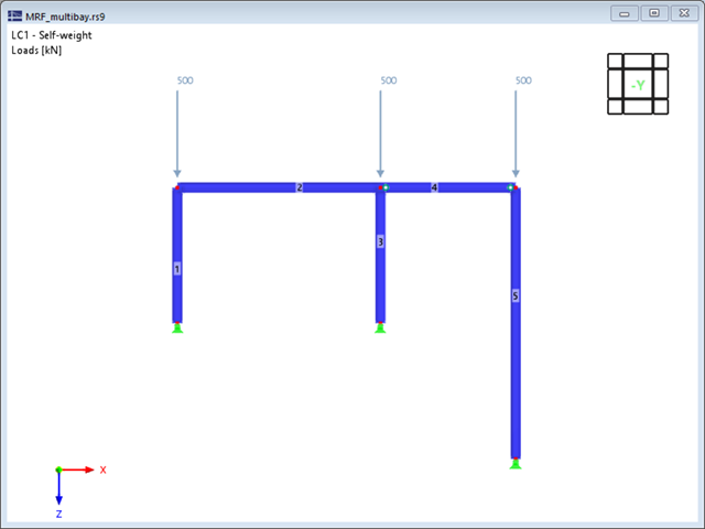
Aby umożliwić ocenę wpływu lokalnych zjawisk stateczności smukłych elementów, w programach RFEM 6 i RSTAB 9 można przeprowadzić liniową analizę obciążenia krytycznego na poziomie przekroju. Poniższy artykuł poświęcony jest podstawom obliczeń i interpretacji wyników.