317 Wyniki
Wyświetl wyniki:
Sortuj według:

Podczas obliczania siły tnącej w programie Wymiarowanie betonu zbrojonego, działającą siłę tnącą Vz można zredukować zgodnie z EN 1992-1-1. Poniższy artykuł opisuje redukcję siły tnącej od obciążeń skupionych w pobliżu podpory oraz wymiarowanie sił tnących w odległości d od krawędzi podpory w przypadku obciążenia równomiernie rozłożonego.

Każdego dnia tysiące inżynierów konstrukcyjnych projektują elementy konstrukcyjne, korzystając z wzorów kontroli projektu, uwzględniających krytyczne obciążenie wyboczeniowe. Ale skąd wzięły się te starożytne wzory, które opracował ponad 200 lat temu i które stanowią podstawę wszystkich trzech koncepcji projektowania konstrukcji stalowych?

Podczas obliczania regularnych konstrukcji wprowadzanie danych często nie jest skomplikowane, ale czasochłonne. Oszczędzaj cenny czas dzięki automatycznemu wprowadzaniu danych. W niniejszym przypadku należy uwzględnić kondygnacje domu jako poszczególne etapy budowy. Dane są wprowadzane przy pomocy programu w języku C#, aby użytkownik nie musiał ręcznie wprowadzać elementów poszczególnych pięter.

W tym artykule pokażemy, jak zdefiniować żebra podłużne na blasze pręta za pomocą komponentu „Żebro” w rozszerzeniu Połączenia stalowe.

Z tego artykułu dowiesz się, jak zamodelować proste połączenie z blachą czołową w programie RFEM 6.

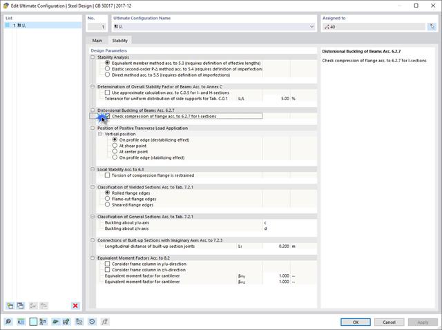
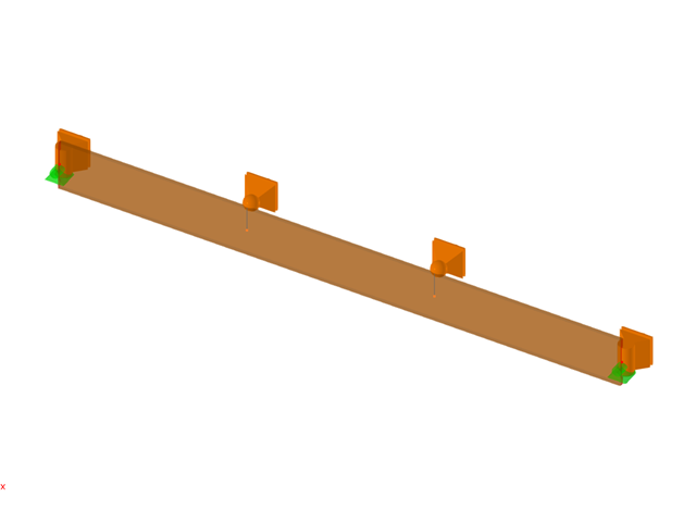
Dzięki rozszerzeniu Projektowanie konstrukcji stalowych możliwe jest projektowanie konstrukcji stalowych zgodnie z normą AISC 360-22. W poniższym artykule porównano wyniki obliczeń zwichrzenia zgodnie z rozdziałem F z analizą wartości własnych.
![Podstawowe kształty konstrukcji membranowych [1]](/pl/webimage/009595/2419506/01-png.png?mw=640&hash=8a9ac87bf3acfb73e6cad970f55eb968a841595c)
Niniejszy artykuł skupia się na specyficznych aspektach projektowania konstrukcji membranowych, które mają specyficzne wymagania, takich jak znajdowanie kształtu (form-finding) i generowanie szablonów cięcia. Integralną częścią projektowania tych konstrukcji jest proces wyszukiwania odpowiednich wstępnie sprężonych kształtów i generowania szablonów cięcia. Tekst krótko opisuje dwa podstawowe procesy w projektowaniu konstrukcji membranowych. Celem jest zilustrowanie ich fizycznego charakteru i zademonstrowanie poszczególnych stwierdzeń za pomocą towarzyszących im przykładów.

Blachownica to ekonomiczny wybór w przypadku konstrukcji o dużych rozpiętościach. I-section steel plate girder typically has a deep web to maximize its shear capacity and flange separation, yet thin web to minimize the self-weight. Due to its large height-to-thickness (h/tw) ratio, transverse stiffeners may be required to stiffen the slender web.

Zrozumienie sztywności połączeń stalowych ma kluczowe znaczenie w projektowaniu konstrukcji. Często połączenia są traktowane jako połączenia całkowicie sztywne lub przegubowe, co może prowadzić do nieekonomicznych lub nawet ryzykownych warunków projektowych. Dowiedz się, w jaki sposób program RFEM firmy Dlubal i rozszerzenie Połączenia stalowe pomagają weryfikować sztywność połączeń i nośność na zginanie, zapewniając bezpieczniejsze i bardziej ekonomiczne warunki projektowe.
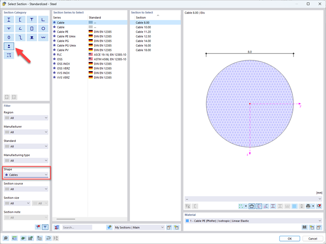
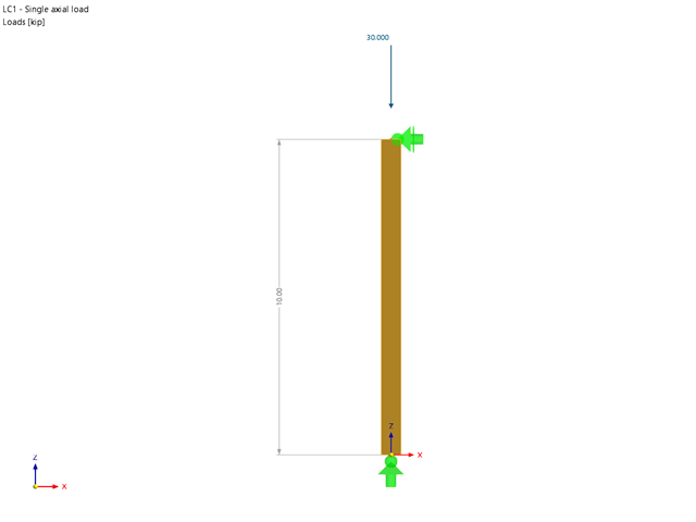
Z tego artykułu dowiesz się, jak modelować i wymiarować konstrukcje kablowe w programach RFEM 6 i RSTAB 9.
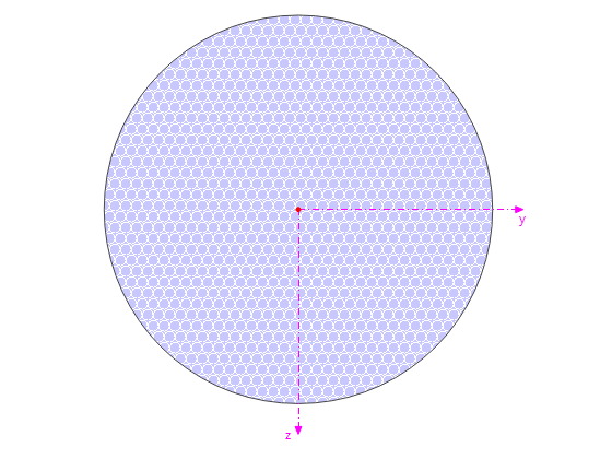
Ten artykuł opisuje i wyjaśnia wpływ sztywności na zginanie kabli na ich siły wewnętrzne. Z tego artykułu dowiesz się również, jak zredukować ten wpływ.

Wyboczenie giętno-skrętne (LTB) jest zjawiskiem, które występuje, gdy belka lub element konstrukcyjny są zginane, a pas ściskany nie jest wystarczająco podparty bocznie. Prowadzi to do kombinacji przemieszczenia bocznego i skręcenia. Jest to decydujący czynnik przy wymiarowaniu elementów konstrukcyjnych, zwłaszcza smukłych belek i dźwigarów.

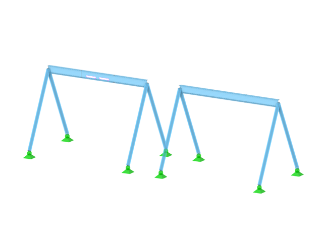
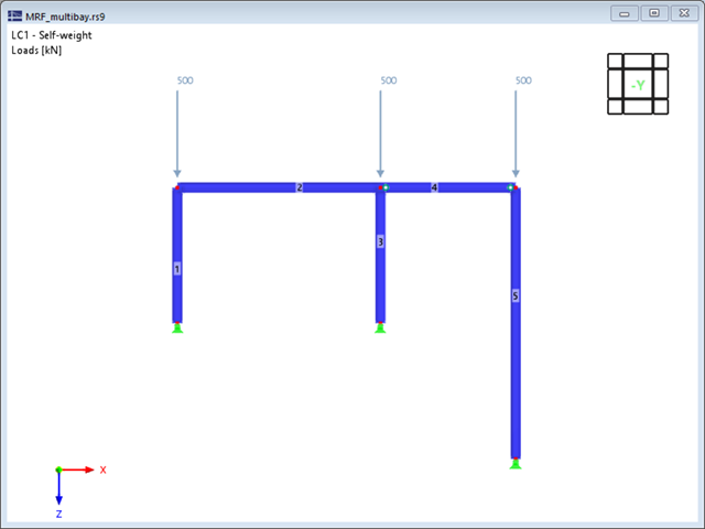
W rozszerzeniu Projektowanie konstrukcji stalowych dla programu RFEM 6 dostępne są trzy typy ram sprężystych (zwykłe, pośrednie i specjalne). Wyniki obliczeń sejsmicznych zgodnie z AISC 341-22 są podzielone na dwie sekcje: wymagania dotyczące prętów i połączeń.
Rozszerzenie Wymiarowanie drewna umożliwia wymiarowanie słupów drewnianych zgodnie ze standardową metodą ASD 2018 NDS. Dokładne wyznaczenie nośności na ściskanie oraz współczynników redukcyjnych dla prętów drewnianych jest konieczne dla bezpieczeństwa konstrukcji. Poniższy artykuł weryfikuje maksymalną wytrzymałość na wyboczenie krytyczną obliczoną w module rozszerzeniowym Wymiarowanie drewna przy użyciu równań analitycznych krok po kroku zgodnie z normą NDS 2018, w tym współczynników dostosowania przy ściskaniu, skorygowanej wartości obliczeniowej na ściskanie i końcowego stopnia wyboczenia.

W tym artykule wyjaśniono, jak działają obliczenia podczas wstępnej analizy sztywności w programie Połączenia stalowe.
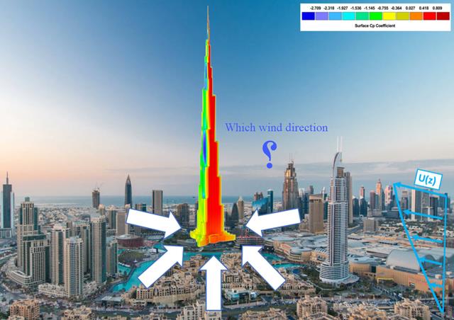
Kierunek wiatru odgrywa kluczową rolę w kształtowaniu wyników symulacji komputerowej mechaniki płynów (CFD) oraz w projektowaniu konstrukcyjnym budynków i infrastruktury. Jest to decydujący czynnik w ocenie interakcji sił wiatru z konstrukcjami, wpływających na rozkład ciśnienia wiatru, a w konsekwencji na reakcje konstrukcji.
Ten przykład pokazuje, jak szybko określić w programie RFEM wyporność lub stan graniczny wyporności dla kontenera.
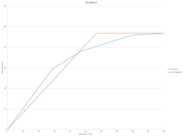
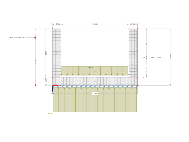
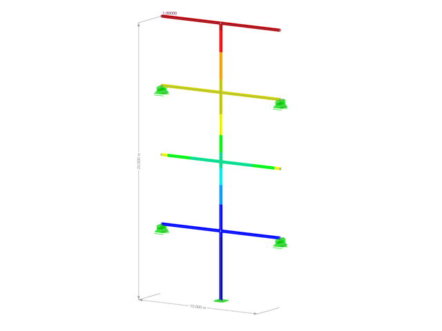
Aby można było przeprowadzić obliczenia push-over, należy zdefiniowaną krzywą nośności przekształcić do postaci uproszczonej. Tak zwana metoda N2 jest opisana w Eurokodzie EN 1998. Ten artykuł powinien pomóc w wyjaśnieniu, co oznacza bilinearyzacja zgodnie z metodą N2.

W tym artykule przedstawiono model połączenia zakładkowego płatwi ZL na dachu jednospadowym, obliczony w rozszerzeniu Połączenia stalowe i porównany z tabelą nośności podaną przez producenta.

Zarówno analiza drgań własnych, jak i analiza spektrum odpowiedzi przeprowadzane są na układzie liniowym. Jeżeli w modelu występują nieliniowości, podlega on linearyzacji, dzięki czemu elementy nieliniowe nie są brane pod uwagę w dalszej analizie. Mogą to być na przykład pręty rozciągane, podpory nieliniowe lub przeguby nieliniowe. W tym artykule pokazano, w jaki sposób można nimi zarządzać w analizie dynamicznej.
Analiza spektrum odpowiedzi jest jedną z najczęściej stosowanych metod obliczeniowych w przypadku obciążenia trzęsieniem ziemi. Metoda ta ma wiele zalet, a najważniejsza z nich to możliwość znacznego uproszczenia obliczeń. Skomplikowany charakter obciążenia jakim jest trzęsienie ziemi jest upraszczany do postaci, która umożliwia przeprowadzenie analizy o rozsądnym stopniu pracochłonności. Wadą metody jest natomiast to, że w wyniku tego uproszczenia traci się część informacji o obciążeniu. Sposobem na zniwelowanie tego ograniczenia może być zastosowanie równoważnej kombinacji liniowej podczas łączenia odpowiedzi modalnych. W poniższym artykule wyjaśniono to bardziej szczegółowo na konkretnym przykładzie.
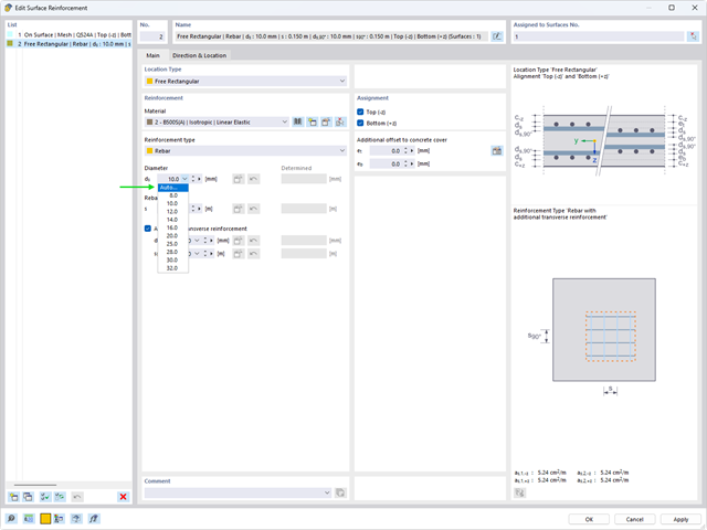
Automatyczny proces wymiarowania zbrojenia określa zbrojenie powierzchniowe, które zapewnia wymaganą ilość zbrojenia wynikającego z obliczeń.

Jeżeli, na przykład, do określenia sił wewnętrznych ma zostać zastosowany model czysto powierzchniowy, ale wymiarowanie komponentu nadal odbywa się na modelu prętowym, można skorzystać z belki wynikowej.
W wielu konstrukcjach szkieletowych zastosowanie prostego pręta nie jest już wystarczające. Często należy wziąć pod uwagę osłabienia przekroju lub otwory w belkach betonowych. Dla takich zastosowań dostępny jest typ pręta "Model powierzchniowy". Można go można zintegrować z modelem jak w przypadku każdego innego pręta i oferuje on wszystkie opcje modelu powierzchniowego. Ten artykuł techniczny pokazuje zastosowanie pręta typu Model powierzchniowy w istniejącym układzie konstrukcyjnym i opisuje integrację otworów pręta.
Modalny współczynnik istotności jest wynikiem analizy stateczności liniowej i opisuje jakościowo stopień udziału poszczególnych prętów w określonym kształcie drgań.
Jeżeli na górnej półce znajduje się płyta betonowa, działa ona jak podpora boczna (konstrukcja zespolona) i zapobiega problemom ze statecznością przy wyboczeniu skrętnym. Jeżeli moment zginający jest ujemny, dolna półka jest obciążona, a górna rozciągana. Jeżeli podparcie boczne nie jest wystarczające ze względu na sztywność środnika, kąt pomiędzy dolną półką a linią nacięcia środnika jest zmienny, przez co istnieje możliwość wystąpienia niestateczności wymiarowej dolnej półki.
W przypadku analizy stateczności prętów przy użyciu metody pręta zastępczego konieczne jest zdefiniowanie długości wyboczeniowej lub zwichrzenia w celu określenia obciążenia krytycznego dla utraty stateczności. W tym artykule przedstawiono funkcję specyficzną dla programu RFEM 6, za pomocą której można przypisać mimośród do podpór węzłowych, a tym samym wpłynąć na określenie krytycznego momentu zginającego uwzględnianego w analizie stateczności.
Połączenia stalowe w programie RFEM 6 można tworzyć poprzez wprowadzenie wstępnie zdefiniowanych komponentów w rozszerzeniu Połączenia stalowe. Lista tych elementów jest stale rozszerzana, aby ułatwić modelowanie połączeń stalowych. W tym artykule przedstawiamy blachę łączącą, która została niedawno dodana do biblioteki rozszerzenia.

Wymiarowanie prętów stalowych formowanych na zimno zgodnie z AISI S100-16 jest teraz dostępne w programie RFEM 6. Design can be accessed by selecting “AISC 360” as the standard in the Steel Design add-on. “AISI S100” is then automatically selected for the cold-formed design (Image 01).
,_Table_22.5.5.1_ACI_318-19.png?mw=640&hash=7e50d54e01238943fe1c691c0aa197d9b2fa8511)
W najnowszej normie ACI 318-19 długoterminowa zależność w określaniu nośności betonu na ścinanieVc zostaje przedefiniowana. Dzięki nowej metodzie wysokość pręta, stopień zbrojenia podłużnego i naprężenie normalne wpływają teraz na wytrzymałość na ścinanie Vc. W poniższym artykule opisano zaktualizowane podejście do obliczeń dla ścinania, a zastosowanie przedstawiono na przykładzie.