109 Wyniki
Wyświetl wyniki:
Sortuj według:

Analiza wyboczenia giętnego jest połączeniem analizy stateczności i stanu granicznego nośności, stosowana w konstrukcjach stalowych od setek lat. Punktem wyjścia do rozważenia kwestii stateczności jest krytyczne obciążenie wyboczeniowe, ale dotychczas nie przeprowadzono obliczeń bez uwzględnienia imperfekcji. Jak dokładnie określane są te imperfekcje?

W artykule przedstawiono równania wykorzystywane przez program do określenia podpór podporowych na podstawie parametrów słupa.

W tym artykule opisano na przykładzie płyty z betonu włóknistego, które wpływają na zastosowanie różnych metod całkowania i różnej liczby punktów całkowania na wynik obliczeń.
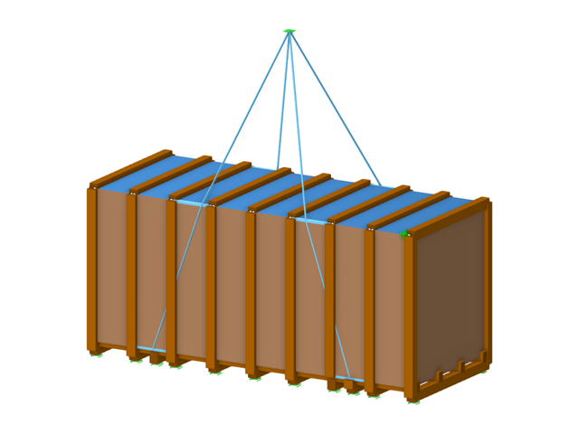
W tym artykule skrzynia na towary ciężkie jest obliczana zgodnie z wytycznymi Bundesverband Holzpackmittel (HPE). Obliczane są przypadki obciążeń dla obsługi dźwigiem i transportu morskiego.
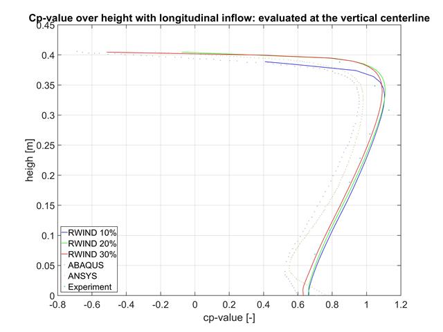
W tym artykule porównujemy wyniki z programów RWIND, ABAQUS i ANSYS z badaniem w tunelu aerodynamicznym przy użyciu prostego geometrycznie modelu.
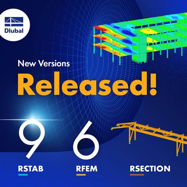
Wraz z programami do analizy statyczno-wytrzymałościowej RFEM 6, RSTAB 9, RSECTION 1 i RWIND 2, Dlubal Software przedstawia nową generację programów do analizy statyczno-wytrzymałościowej. Getreu dem Motto „Statik, die Spaß macht…“ werden den Anwendern universelle Werkzeuge in die Hand gegeben, mit denen alle Anforderungen in der Tragwerksplanung bewältigt werden können. Was sich sonst noch bei Dlubal Software Neues getan hat, erfahren Sie in diesem Artikel.
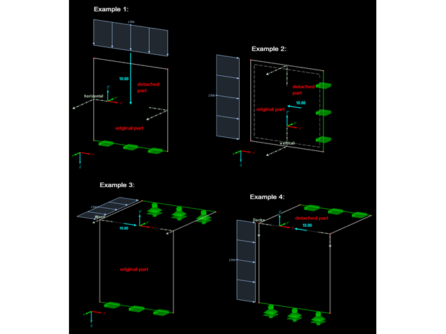
In RFEM gibt es die Möglichkeit, sich die Resultierende eines Schnittes beziehungsweise einer Freigabe ausgeben zu lassen. In diesem Beitrag soll geklärt werden, auf welchen Teil der Schnittfläche diese wirkt. Am einfachsten wäre es, die Resultierende auf ein Schnittufer der Fläche zu beziehen. Da jedoch ein Schnitt auch durch mehrere Flächen mit unterschiedlichen lokalen Koordinatensystemen verlaufen kann, ist die Aussage mittels Schnittufer nicht möglich.
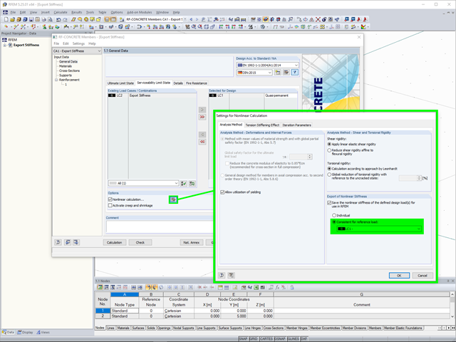
Wird ein Stahlbetonmodell als gemischte Struktur, bestehend aus Flächen- und Stabelementen, abgebildet, so werden für die weitere Bemessung unterschiedliche Module verwendet.
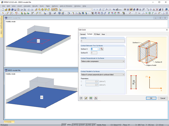
Die Kontakteigenschaften zwischen zwei Flächen können in RFEM mit Hilfe von Kontaktvolumen abgebildet werden. Bei der Modellierung ist unter anderem zu beachten, dass in der Regel beide Kontaktflächen eines Kontaktvolumens die gleichen integrierten Objekte aufweisen sollten. Es empfiehlt sich daher, gleich bei der Anlage der Kontaktflächen die zweite Kontaktfläche durch Kopieren zu erstellen.
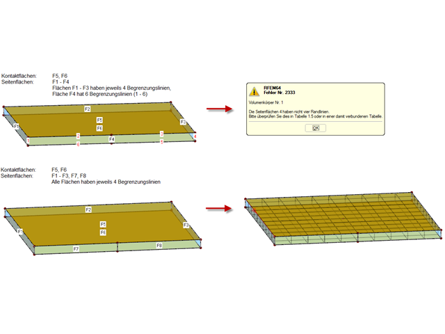
Die Kontakteigenschaften zwischen zwei Flächen können in RFEM mit Hilfe von Kontaktvolumen abgebildet werden.
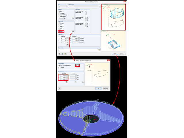
Für die schnelle Generierung von radialen Flächenlasten steht in RFEM im Dialog der Lastverlauf "Radial" zur Verfügung.
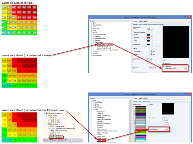
Um eine übersichtlichere Darstellung der Ergebniswerte zu erzielen, können verschiedene Einstellungen vorgenommen werden. Einige Anwender stört beispielsweise der weiße Hintergrund in den Textblasen. Dieser Hintergrund kann in den "Anzeigeeigenschaften" über die Transparenz und über die Hintergrundfarbe gesteuert werden.
Das Einfügen von Löchern in Flächen ist durch eine große Auswahl an Werkzeugen sehr einfach. Um bei Volumen Löcher oder Bohren einzufügen, ist zu beachten, dass bei einem durchgehendem Loch am Anfang und am Ende eine Öffnung erstellt werden muss und zudem eine Fläche, welche das Loch von dem Volumen abtrennt.
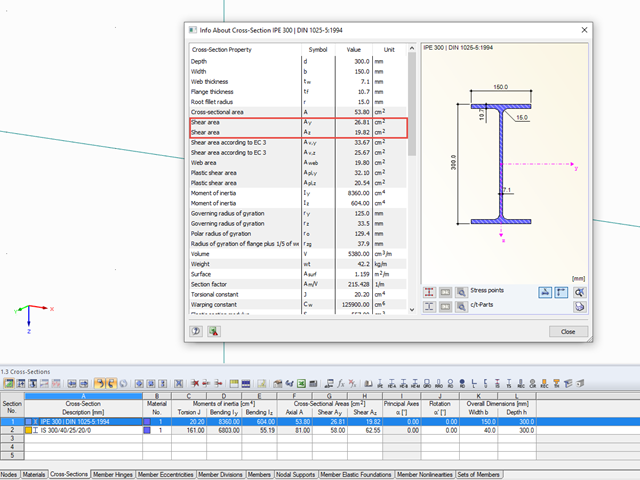
Właściwości przekrojów w RFEM i RSTAB uwzględniają różne typy powierzchni ścinania. W tym artykule technicznym wyjaśniono sposób obliczania i znaczenie różnych wartości.
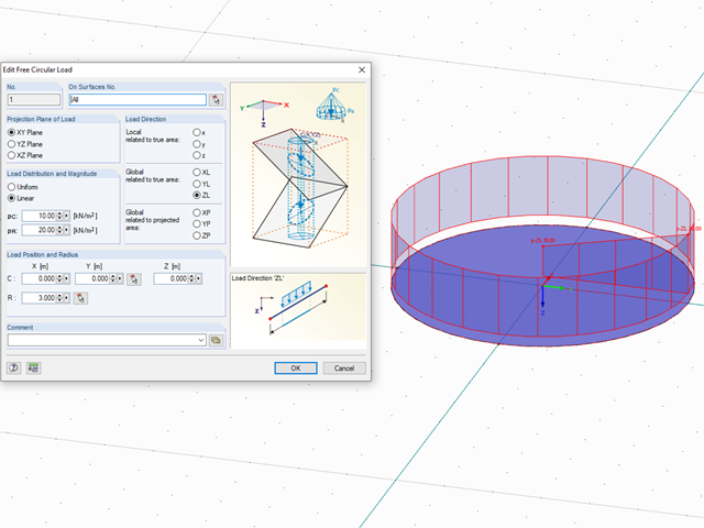
In RFEM können Belastungen frei auf Flächen definiert werden. Dabei ist es nicht direkt möglich, beispielsweise auf Kreisflächen eine veränderliche radiale Belastung zu definieren. Mit einem kleinen Trick lässt sich diese Art der Belastung aber trotzdem erstellen, nämlich durch Verwendung einer freien Kreislast.
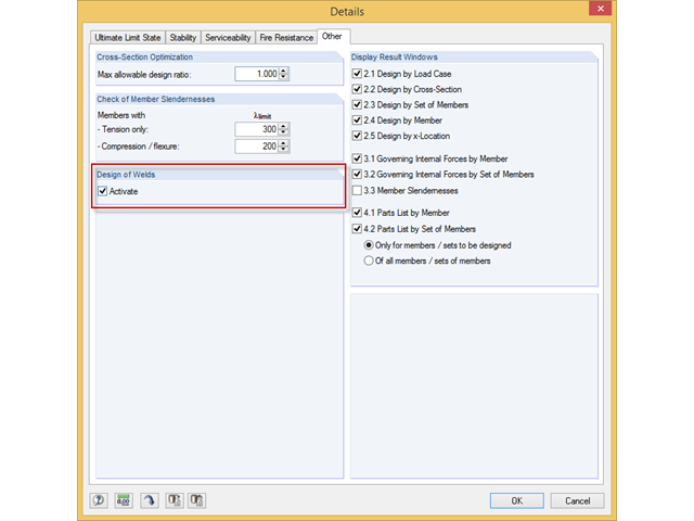
Das Zusatzmodul RF-/STAHL EC3 kann den Nachweis der Halskehlnähte für alle parametrischen, geschweißten Querschnitte der Querschnittsbibliothek führen. Hierzu muss die Option in den Detaileinstellungen des Moduls aktiviert werden. Alternativ kann auch ein Flächenmodell zur Bemessung genutzt werden.
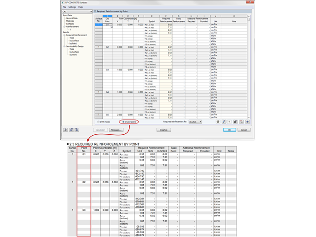
Die Ergebnisse aus RF-BETON Flächen können im Ausdruckprotokoll tabellarisch dokumentiert werden.
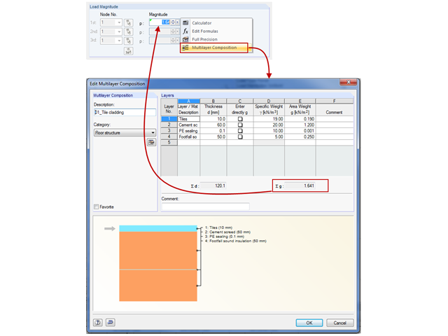
Die zusätzlichen Lasten aus Eigengewicht setzen sich in der Regel aus mehreren Schichten zusammen, wie zum Beispiel dem klassischen Fußboden- und Dachaufbau im Hochbau oder dem Fahrbahnaufbau bei Brückentragwerken. Bei der Lastdefinition in RFEM und RSTAB können mittels Verwendung der Mehrschichtaufbau-Last die einzelnen Schichten mit Dicke und spezifischem Gewicht definiert werden.
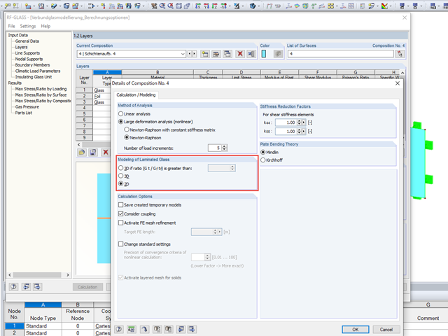
Bei der Glasbemessung im Zusatzmodul RF-GLAS stehen grundsätzlich zwei verschiedene Berechnungsoptionen zur Verfügung: eine 2D- und eine 3D-Berechnung. Grundsätzlicher Unterschied dieser beiden Bemessungsvarianten ist die vom Programm automatisierte Modellierung der Scheiben im temporären Modell. Bei einer 2D-Bemessung werden für die einzelnen Scheiben gängige Flächenelemente (Plattentheorie) generiert, während bei der 3D-Bemessung die einzelnen Scheiben als Volumen abgebildet werden. Je nach gewähltem Schichtaufbau steht die Option zur Wahl oder wird vom Programm bereits automatisch vorgegeben.
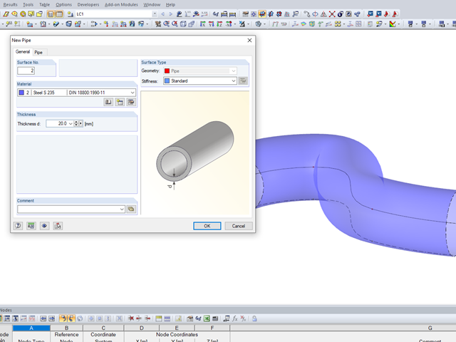
Speziell im Anlagenbau, aber auch bei der Detailbetrachtung von statischen Strukturen kann es notwendig werden, Rohrquerschnitte als Flächenmodelle analysieren zu müssen. Für diese Zwecke bietet RFEM die Möglichkeit, anhand einer Linie automatisch Rohrquerschnitte zu erzeugen.
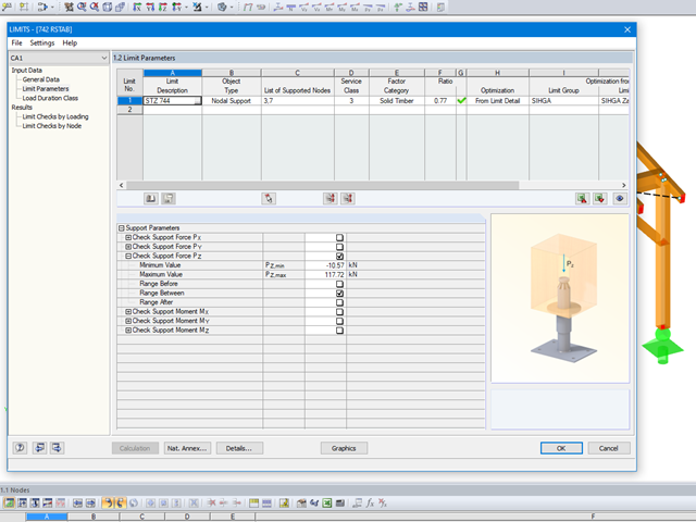
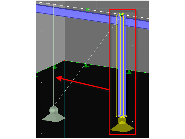
Mit dem Modul LIMITS ist es möglich die Tragfähigkeit von Stäben, Stabenden, Knoten, Knotenlagern und Flächen (nur RFEM) anhand einer definierten Grenztragfähigkeit zu vergleichen. Des Weiteren können Knotenverschiebungen sowie Querschnittsabmessungen kontrolliert werden. In diesem Beispiel sollen Stützenfüße eines Carports mit den vom Hersteller angegebenen, maximal zulässigen, Kräften verglichen werden.
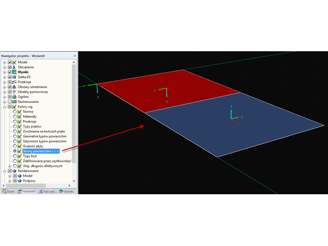
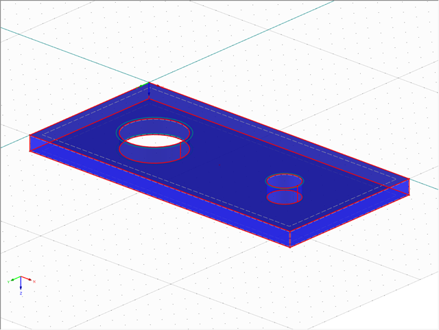
Über die entsprechende Option im "Zeigen-Navigator" können die Flächen im Rendering nach der Richtung der lokalen z-Achse eingefärbt werden. Standardmäßig werden die Seite, die in negativer z-Richtung liegt, rot und die diejenige, die in positiver z-Richtung liegt, blau eingefärbt.
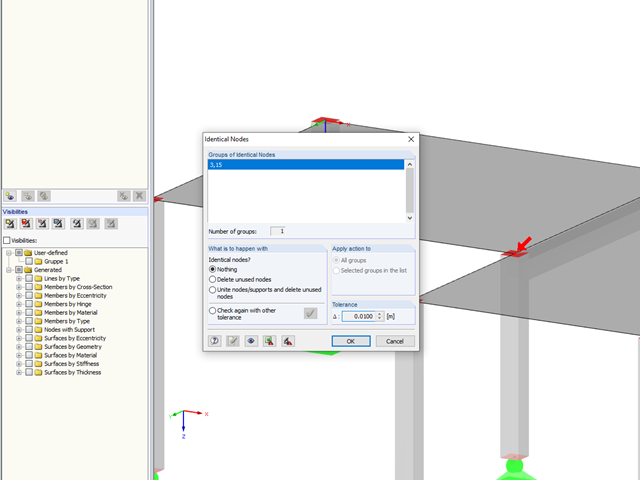
In RFEM 5 und RSTAB 8 ist es möglich, die bei einer Modellkontrolle auftretenden Probleme und Warnungen extra als Ansicht zu speichern. Damit kann man auf einfachem Wege die Hinweise nacheinander abarbeiten und das Modell bereinigen. Diese Funktion ist für doppelte Knoten, überlappende Stäbe/Linien und Flächen vorhanden.
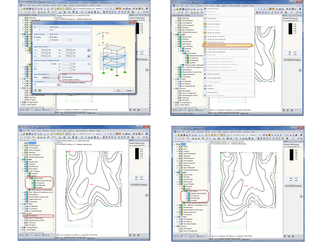
Die Ergebnisse einer FEM-Berechnung werden in der Regel mit einer grafischen Ergebnisdarstellung mittels Isoflächen oder Isolinien dokumentiert. Im nachfolgenden Beitrag wird die Vorbereitung der Ergebnisgrafik mit Isolinien für den Schwarz-Weiß-Ausdruck näher erläutert.
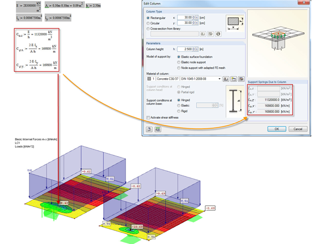
Damit Singularitäten infolge eines festen Knotenlagers in RFEM vermieden werden können, gibt es die die Möglichkeit einer elastischen Lagerung. Diese kann direkt im Dialog des Knotenlagers als Stütze in Z definiert werden. Dabei müssen die Geometrie der Stütze sowie das Material und die Lagerungsbedingungen erfasst werden. In diesem Beitrag soll die Variante der Modellierung der Stütze als Flächenbettung gezeigt werden.
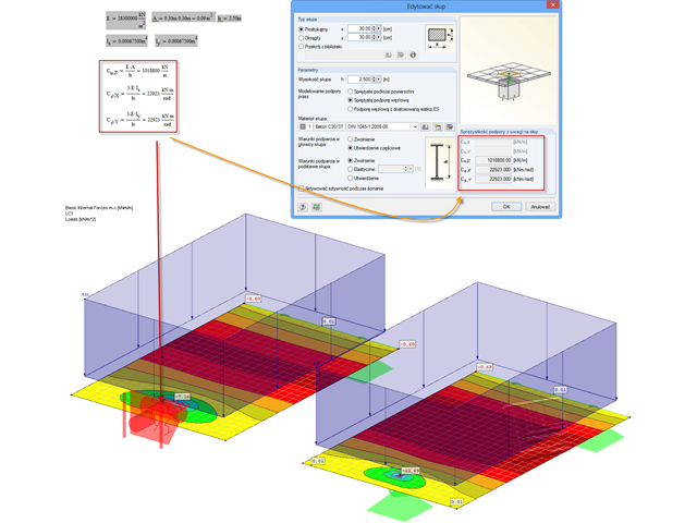
Często w czasie projektowania spotykamy się z tak zwanymi koncentracjami naprężeń w płytach nad podporami. Diese Singularitäten kann man umgehen, indem man das Knotenlager als Stütze modelliert.
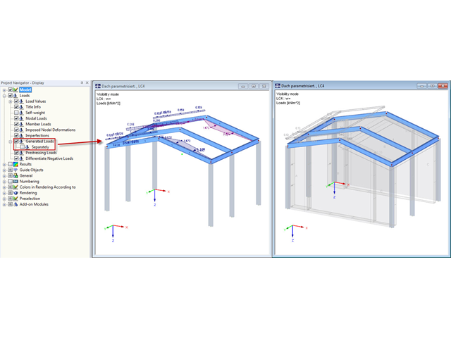
Befindet man sich im Sichtbarkeitsmodus nach der Definition von zusammengehörigen generierten Lasten, werden diese bei der Darstellung als Flächenlast auch an den ausgeblendeten Strukturteilen angezeigt.
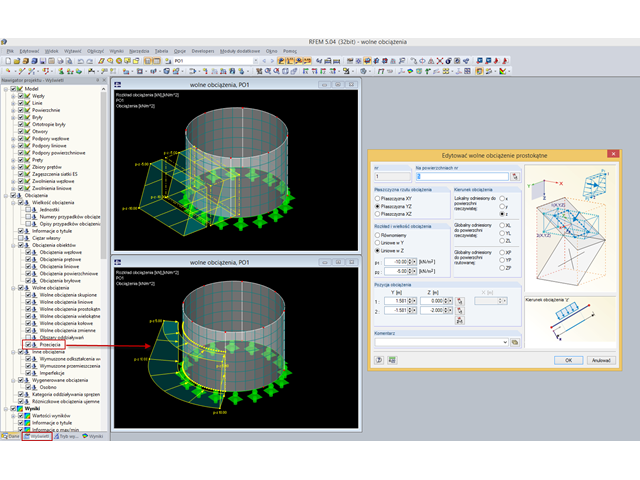
Häufig müssen in RFEM nur Teile und nicht die gesamte Fläche belastet werden. Klassischer Fall dazu ist der Erddruck. Dafür gibt es die Möglichkeit der freien Flächenlasten. Diese sind dann flächenunabhängig und werden in der Grafik in den definierten Koordinatenabmessungen dargestellt.
Lager können mittels Drag & Drop kopiert und verschoben werden, auch wenn im Kontextmenü die Funktion "Verschieben/Kopieren" nicht angeboten wird. Das trifft auf alle Arten von Lagern zu: węzłowych, liniowych, powierzchniowych. Diese können so auf einfache Art und Weise weiteren Knoten beziehungsweise Linien oder Flächen zugewiesen werden.
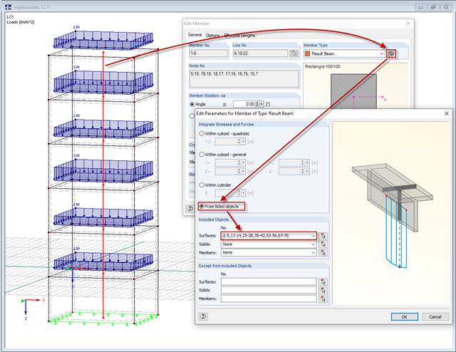
Mit dem neuen Stabtyp "Ergebnisstab" in RFEM 5 hat man nun auch die Möglichkeit, sich die Lastsummen einzelner Geschosse einfach ermitteln zu lassen. Dazu modelliert man einen Stab in dem gewünschten oder in allen Geschossen und gibt bei den Parametern des Ergebnisstabes die zu berücksichtigenden Wände als inklusive Objekte vor. RFEM integriert dann die Flächenschnittgrößen zu Stabschnittgrößen.