73 Wyniki
Wyświetl wyniki:
Sortuj według:

Parametry załączników krajowych (NA) do Eurokodu 3 z następujących krajów są zintegrowane:
-
 DIN EN 1993-1-1/NA:2016-04 (Niemcy)
 -
 ÖNORM EN 1993-1-1/NA:2015-12 (Austria)
 -
 SN EN 1993-1-1/NA:2016-07 (Szwajcaria)
 -
 BDS EN 1993-1-1/NA:2015-10 (Bułgaria)
 -
 BS EN 1993-1-1/NA:2016-07 (Wielka Brytania)
 -
 CEN EN 1993-1-1/2015-06 (Unia Europejska)
 -
 CYS EN 1993-1-1/NA:2015-07 (Cypr)
 -
 CSN EN 1993-1-1/NA:2016-06 (Republika Czeska)
 -
 DS EN 1993-1-1/NA:2015-07 (Dania)
 -
 ELOT EN 1993-1-1/NA:2017-01 (Grecja)
 -
 EVS EN 1993-1-1/NA:2015-08 (Estonia)
 -
 HRN EN 1993-1-1/NA:2016-03 (Chorwacja)
 -
 I S. EN 1993-1-1/NA:2016-03 (Irlandia)
 -
 ILNAS EN 1993-1-1/NA:2015-06 (Luksemburg)
 -
 IST EN 1993-1-1/NA:2015-11 (Islandia)
 -
 LST EN 1993-1-1/NA:2017-01 (Litwa)
 -
 LVS EN 1993-1-1/NA:2015-10 (Łotwa)
 -
 MS EN 1993-1-1/NA:2010-01 (Malezja)
 -
 MSZ EN 1993-1-1/NA:2015-11 (Węgry)
 -
 NBN EN 1993-1-1/NA:2015-07 (Belgia)
 -
 NEN EN 1993-1-1/NA:2016-12 (Holandia)
 -
 NF EN 1993-1-1/NA:2016-02 (Francja)
 -
 NP EN 1993-1-1/NA:2009-03 (Portugalia)
 -
 NS EN 1993-1-1/NA:2015-09 (Norwegia)
 -
 PN EN 1993-1-1/NA:2015-08 (Polska)
 -
 SFS EN 1993-1-1/NA:2015-08 (Finlandia)
 -
 SIST EN 1993-1-1/NA:2016-09 (Słowenia)
 -
 SR EN 1993-1-1/NA:2016-04 (Rumunia)
 -
 SS EN 1993-1-1/NA:2019-05 (Singapur)
 -
 SS EN 1993-1-1/NA:2015-06 (Szwecja)
 -
 STN EN 1993-1-1/NA:2015-10 (Słowacja)
 -
 TKP EN 1993-1-1/NA:2015-04 (Białoruś)
 -
 UNE EN 1993-1-1/NA:2016-02 (Hiszpania)
 -
 UNI EN 1993-1-1/NA:2015-08 (Włochy)
_(1).png?mw=640&hash=415f7bbaf70e41679bb0106e1cf91eaa8c493ec9)
- Automatyczne generowanie modeli do analizy ES: rozszerzenie automatycznie tworzy w tle model elementów skończonych (ES) połączenia stalowego.
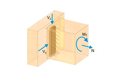
- Uwzględnienie wszystkich sił wewnętrznych: Obliczenia obejmują wszystkie siły wewnętrzne (N , Vy, Vz ,My, Mz, MT ) i nie są ograniczone do obciążeń płaskich.
- Automatyczne przenoszenie obciążeń: Wszystkie kombinacje obciążeń są automatycznie przenoszone do modelu analitycznego ES połączenia. Obciążenia są przenoszone bezpośrednio z programu RFEM, dzięki czemu ręczne wprowadzanie danych nie jest konieczne.
- Wydajne modelowanie: Rozszerzenie pozwala zaoszczędzić czas podczas modelowania złożonych sytuacji związanych z połączeniami. Utworzony model analityczny ES można również zapisać i wykorzystać do własnych szczegółowych analiz.
- Rozszerzalna biblioteka: Dostępna jest obszerna, rozszerzalna biblioteka zawierająca wstępnie zdefiniowane szablony połączeń stalowych.
- Szerokie zastosowanie: Rozszerzenie jest odpowiednie do tworzenia połączeń każdego typu i kształtu, jest kompatybilne z prawie wszystkimi przekrojami walcowanymi, spawanymi, złożonymi i cienkościennymi.
Najpierw wyświetlane są decydujące obliczenia połączenia dla danego przypadku obciążenia oraz kombinacji obciążeń lub kombinacji wyników. Ponadto możliwe jest oddzielne wyświetlanie wyników dla zbiorów prętów, przekrojów, prętów, węzłów i podpór węzłowych.
- Możesz użyć filtra, aby jeszcze bardziej zredukować wyświetlane wyniki, a tym samym przedstawić je w bardziej przejrzysty sposób.
- Wymiarowanie końców, prętów, podpór węzłowych, węzłów i powierzchni
- Uwzględnienie określonych obszarów obliczeniowych
- Kontrola wymiarów przekroju
- Wymiarowanie według EN 1995-1-1 (Europejska norma dotycząca drewna) zgodnie z odpowiednimi załącznikami krajowymi + DIN 1052 + DSTV DIN EN 1993-1-8 + ANSI/AWC - NDS 2015 (norma amerykańska)
- Projektowanie różnych materiałów, takich jak stal, beton i inne
- Nie ma konieczności łączenia się z konkretnymi normami
- Rozszerzalna biblioteka o elementy łaczące z drewna (SIHGA, Sherpa, WÜRTH, Simpson StrongTie, KNAPP, PITZL) i elementy stalowe (połączenia znormalizowane w konstrukcjach stalowych zgodnie z EC 3, M-connect, PFEIFER, TG-Technik)
- Nośności graniczne belek drewnianych firm STEICO i Metsä Wood dostępne w bibliotece
- Połączenie z MS Excel
- Optymalizacja elementów łączących (obliczany jest element najczęściej wykorzystywany)
.png?mw=640&hash=c9c52de2eed98a2905a02fbf54b073f645c0df2c)
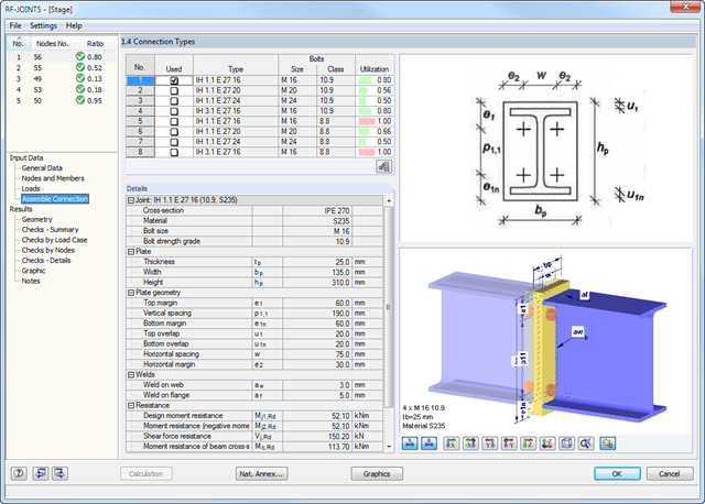
- Obliczanie połączeń przenoszących moment oraz przegubowych dla walcowanych przekrojów w kształcie litery I, według Eurokodu 3:
- Połączenia z blachą czołową przenoszącą moment (typ IH/IM)
- Połączenia przegubowe spawane (typ PM)
- Połączenia proste z kątownikami normalnymi lub nierównoramiennymi (typ IW lub IG)
- Proste połączenia przy użyciu blach czołowych zamontowanych tylko na środniku bądź na środniku i pasach (typ IS)
- Możliwość łączenia połączeń w wycięciem (IK) z przegubowymi płytami czołowymi (IS) oraz z połączeniami łącznikiem środnikowym (IW)
- Automatyczne rozmieszczenie śrub dla danego połączenia (dla wszystkich typów)
- Sprawdzanie wymaganej grubości pręta przenoszącego obciążenie w połączeniach ścinanych
- Podawanie wszystkich wymaganych szczegółów konstrukcyjnych, takich jak urządzenia, układ otworów, potrzebnych wysięgników, ilość śrub, wymiary płyty czołowej oraz spoin
- Podawanie sztywności S j,ini dla połączeń przenoszących zginanie
- Dokumentacja dostępnych obciążeń i porównywanie ich z nośnościami
- Podawanie stopnia wykorzystania dla każdego pojedynczego połączenia
- Automatyczne określanie głównych sił wewnętrznych dla kilku przypadków obciążeń oraz węzłów połączeniowych
- Integracja z RFEM/RSTAB z automatycznym rozpoznawaniem geometrii i przenoszeniem sił wewnętrznych
- Możliwość ręcznego definiowania połączeń
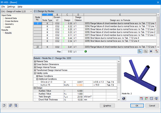
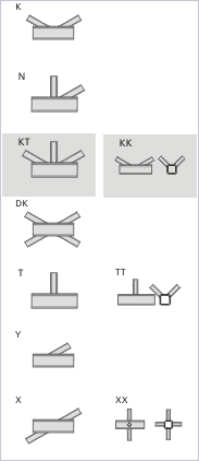
- Obszerna biblioteka przekrojów rurowych dla pasów i stężeń:
- przekroje okrągłe
- przekroje kwadratowe
- przekroje prostokątne
- Dostępne klasy stali: S 235, S 275, S 355, S 420, S 450 oraz S 460
- W zależności od specyfikacji standardowej dostępne są różne typy połączeń:
- Połączenie K (przerwa/przekrycie)
- Połączenie KK (przestrzenne)
- Połączenie N (przerwa/przekrycie)
- Połączenie KT (przerwa/przekrycie)
- Połączenie DK (przerwa/przekrycie)
- Połączenie T (płaszczyznowe)
- Połączenie TT (przestrzenne)
- Połączenie Y (płaszczyznowe)
- Połączenie X (płaszczyznowe)
- Połączenie XX (przestrzenne)
- Wybór częściowych współczynników bezpieczeństwa zgodnie z załącznikiem krajowym dla Niemiec, Austrii, Czech, Słowacji, Polski, Słowenii, Szwajcarii i Danii
- Dostosowywanie kątów pomiędzy pasami i stężeniami
- Opcjonalny obrót pasów o 90° dla prostokątnych przekrojów rurowych
- Możliwość uwzględniania przerw pomiędzy stężeniami lub ich wzajemnego pokrywania się
- Opcjonalne uwzględnianie dodatkowych sił węzłowych
- Obliczanie połączenia jako maksymalna nośność krzyżulców kratownicy dla sił osiowych i momentów zginających
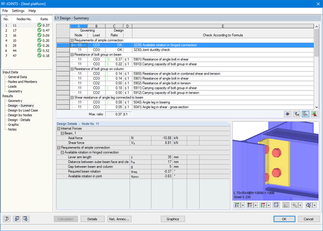
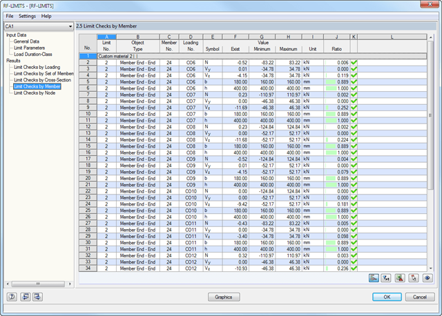
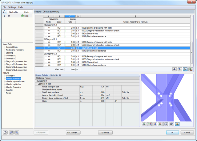
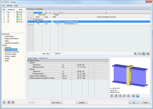
W oknach wyników wyszczególnione są wszystkie wyniki obliczeń. Ponadto tworzone są grafiki 3D, w których poszczególne elementy oraz linie wymiarowe można wyświetlać lub ukrywać. W podsumowaniu można sprawdzić, czy potwierdzono poprawność obliczeń: Stopień wykorzystania jest dodatkowo wizualizowany za pomocą zielonego paska danych, który zmienia kolor na czerwony, gdy obliczenia nie są spełnione. Ponadto wyświetlany jest numer węzła i decydujące PO/KO/KW.
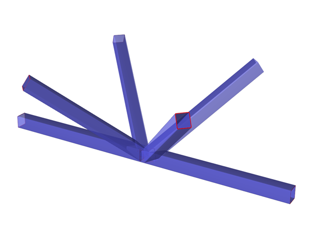
Podczas wyboru obliczeń wyświetlane są szczegółowe wyniki pośrednie wraz z oddziaływaniami i dodatkowymi siłami wewnętrznymi wynikającymi z geometrii połączenia. Istnieje możliwość wyświetlenia wyników według przypadków obciążeń i węzłów. Połączenia są przedstawione w realistycznym renderingu 3D, który można skalować. Oprócz głównych widoków, połączenie można zobaczyć z każdej strony.
Grafiki z wymiarami i opisami można dodać do wydruku programu RFEM/RSTAB lub eksportować jako DXF. Protokół wydruku zawiera wszystkie dane wejściowe i wyniki, przygotowane dla inżynierów testujących. Wszystkie tabele można wyeksportować do programu MS Excel lub do pliku CSV. Wszystkie dane wymagane do eksportu definiuje się w specjalnym menu dla transferu.
Po dokonaniu analizy moduł RF-/JOINTS Steel - Column Base pokazuje następujące obliczenia:
- Wymiarowanie przekroju netto
- Obliczenie docisku
- Siły tnące
- Nośność blokowa
- poślizg
- Stosuje się do prętów zdefiniowanych jako zbiory prętów
- Oddzielny solwer uwzględniający 7 kierunków deformacji (ux , uy, uz, φx, φy, φz, ω ) lub 8 sił wewnętrznych (N, Vu, Vv, Mt, pri, Mt, s, Mu, Mv,M )
- Projektowanie nieliniowe według analizy drugiego rzędu
- Wprowadzanie imperfekcji
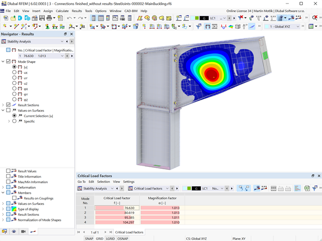
- Obliczanie współczynników obciążenia krytycznego i postaci wyboczenia oraz ich wizualizacja (wraz z skręcaniem skrępowanym)
- Integracja z wymiarowaniem prętów w modułach dodatkowych RF-/STEEL AISC i RF-/STEEL EC3
- Dostępne dla wszystkich przekrojów stalowych cienkościennych
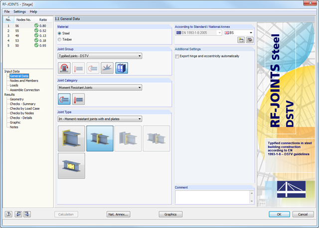
Po otwarciu modułu dodatkowego należy wybrać typ połączenia (przegubowe lub przegubowe połączenie z belką dwuteową). Poszczególne węzły można wybrać graficznie w modelu programu RFEM/RSTAB.
Moduł dodatkowy RF-/JOINTS Steel - DSTV automatycznie rozpoznaje przekrój wraz z odpowiednim materiałem i sprawdza, czy możliwe jest wymiarowanie połączenia zgodnie z wytycznymi DSTV. Ponadto można modelować i wymiarować połączenia o podobnej konstrukcji w kilku miejscach konstrukcji belki.
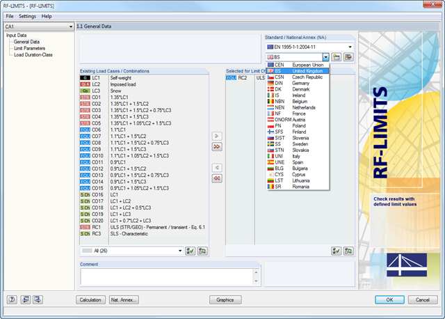
Po wybraniu obciążeń wymaganych do obliczeń oraz, w razie potrzeby, żądanej normy do obliczeń, w oknie 1.2 Parametry graniczne można zdefiniować obciążenia graniczne. Możliwe jest dodawanie innych producentów do listy w bazie danych.
Po wybraniu wszystkich elementów granicznych do obliczeń można opcjonalnie zdefiniować klasę trwania obciążenia (KTO). Trzecie okno modułu jest dostępne jedynie w przypadku wymiarowania elementów połączeń drewnianych wg EN 1995-1-1 lub DIN 1052.

- Wybór węzłów w modelu RFEM, automatyczne rozpoznawanie i przydzielanie prętów połączonych z wybranym węzłem
- Dostępnych jest wiele wstępnie zdefiniowanych elementów ułatwiających wprowadzanie typowych komponentów połączeń (np. blachy czołowe, żebra usztywniające)
- Uniwersalne komponenty bazowe (płyty, spoiny, płaszczyzny pomocnicze) do odwzorowania złożonych geometrii połączeń
- Użytkownik nie musi ręcznie edytować modelu MES połączenia, podstawowe ustawienia obliczeń można zmienić w oknie konfiguracji połączenia
- Automatyczne dostosowywanie geometrii połączenia, nawet w przypadku późniejszej edycji prętów, z uwagi na parametryczną definicję położenia komponentów względem siebie
- Równolegle do wprowadzania danych program przeprowadza kontrolę poprawności, aby szybko wykryć brakujące dane wejściowe lub kolizje elementów.
- Wizualizacja geometrii połączenia, która jest aktualizowana równolegle z wprowadzaniem danych
.png?mw=640&hash=eaf8e422e9b3dcfb04a920c1d3bf09c1bef0d59a)
Ogólne informacje
- Połączenie typu belka-słup: możliwe połączenie na pasie lub na środniku słupa
- Połączenie typu belka-belka: możliwość rozmieszczenia żeber po przeciwnej stronie
- Rozmiary śrub od M12 do M36 z klasami wytrzymałości 4.6, 5.6, 8.8 oraz 10.9
- Dowolny rozstaw otworów na śruby i odległości od krawędzi
- Możliwe jest podcięcie belki
- Połączenie z czystym obciążeniem ścinającym, czystym obciążeniem siłą normalną (styk rozciągany) lub możliwymi kombinacjami sił normalnych i tnących
- Sprawdzenie zgodności z wymaganiami dla połączeń przegubowych
- Sprawdzenie minimalnego i maksymalnego rozstawu otworów na śruby oraz odległości od krawędzi
Połączenia nakładkowe ze środnikiem
- Możliwość zastosowania jednego lub dwóch pionowych i do 10 poziomych rzędów śrub na każdym ramieniu
- Szeroki zakres kątów równoramiennych i nierównoramiennych
- Możliwość modyfikacji orientacji kąta
- Wyk. przekroju:
- Obliczanie śrub . na ścinanie, docisk i rozciąganie
- Obliczenia na ścinanie, zginanie i rozciąganie kątowników z uwzględnieniem odliczenia otworu na śrubę
- Obliczanie ścinania i rozciągania środnika dźwigara z uwzględnieniem odliczenia otworu na śrubę
- Przenoszenie rozciągania na słup w modelu z króćcem teowym
- Podcięcie w przekroju krytycznym
Połączenie z przykładką środnika
- Możliwy jest jeden lub dwa pionowe rzędy śrub oraz do 10 poziomych rzędów śrub
- Elastyczny rozmiar blachy środnika
- Możliwość modyfikacji położenia blachy środnika
- Wyk. przekroju:
- Obliczanie nośności na ścinanie i docisk śrub
- Obliczenia na ścinanie, zginanie i rozciąganie płyt środnika z uwzględnieniem odliczenia otworu na śrubę
- Analiza stateczności długich, smukłych płyt
- Obliczanie ścinania i rozciągania środnika dźwigara z uwzględnieniem odliczenia otworu na śrubę
- Spoina jako spoina pachwinowa
- Podcięcie w przekroju krytycznym
Połączenie przy użyciu płyty czołowej
- Dwa lub cztery pionowe rzędy śrub i maks. 10 poziomych rzędów śrub
- Elastyczny rozmiar blachy czołowej
- Możliwość modyfikacji położenia blachy środnika
- Wyk. przekroju:
- Obliczanie śrub . na ścinanie, docisk i rozciąganie
- Obliczanie ścinania i zginania blach czołowych z uwzględnieniem odliczenia otworu na śrubę
- Obliczenia przy ścinaniu i rozciąganiu środnika dźwigara
- Przenoszenie rozciągania na słup w modelu z króćcem teowym
- Spoina jako spoina pachwinowa
- Podcięcie w przekroju krytycznym
Połączenie z blachą czołową i nakładką
- Mocowanie belki za pomocą blachy czołowej za pomocą dwóch śrub
- Elastyczny rozmiar nakładki i blachy czołowej
- Wyk. przekroju:
- Wprowadzenie obciążenia na belkę zgodnie z EN 1993-1-5, Rozdział 6
- Podparcie momentu stabilizującego za pomocą śrub i spoin na płycie czołowej
- Nakładka
- Spoiny nakładkowe jako spoiny pachwinowe
- Przenoszenie rozciągania na słup w modelu z króćcem teowym
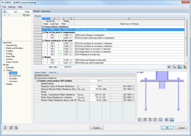
Po dokonaniu analizy moduł RF-/JOINTS Steel - Column Base pokazuje następujące obliczenia:
- Wytrzymałości na zginanie podstawy słupa
- Rozciągania kotew oraz siły ścinające w kotwach
- Wytrzymałości na scinanie klina
- Ściskania betonu / zniszczenia krawędzi betonu
- Tarcie
- Spoiny
Po wybraniu w pierwszym oknie danych typu połączenia, kategorii połączenia oraz normy obliczeniowej, w oknie 1.2 można zdefiniować węzeł, który zostanie zaimportowany z programu RFEM/RSTAB i użyty do obliczeń połączenia. Opcjonalnie geometrię połączenia można zdefiniować ręcznie.
W kolejnych oknach wprowadzania można zdefiniować parametry połączenia, takie jak np. wprowadzenie obciążenia z programu RFEM/RSTAB lub, w przypadku ręcznego definiowania połączenia, obciążeń.
Wyniki zawierają szczegółowe informacje na temat analizowanych sił wewnętrznych, kryteriów obliczeniowych oraz granic. Niezadowalające wyniki obliczeń są jasno zaznaczone.
Wszystkie dane początkowe i wyniki są również udokumentowane w ogólnym protokole wydruku programu RFEM/RSTAB. Oddzielne przypadki obliczeniowe pozwalają na elastyczne badanie poszczególnych części dużych konstrukcji.
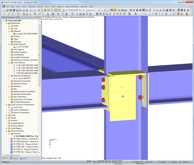
Po pierwsze, moduł łączy w sobie decydujące obliczenia dla słupa i belki poziomej oraz wyświetla geometrię połączenia w tabeli wyników. Inne tabele wyników zawierają wszystkie ważne szczegóły obliczeń, takie jak długości linii płynięcia, nośność śrub, naprężenia w spoinach lub sztywności połączeń. Wszystkie połączenia przedstawiane są w graficznym renderowaniu 3D.
Wymiary, specyfikacje materiałowe i spoiny, które są istotne dla konstrukcji połączenia, są widoczne od razu i można je wydrukować. Połączenia można przedstawić graficznie w dodatkowym module RF-/FRAME-JOINT Pro lub bezpośrednio w modelu programu RFEM/RSTAB. Wszystkie grafiki mogą zostać dołączone do protokołu wydruku programu RFEM/RSTAB lub wydrukowane bezpośrednio. Dzięki skalowaniu wyników, możliwa jest optymalna kontrola wizualna już na etapie projektowania.
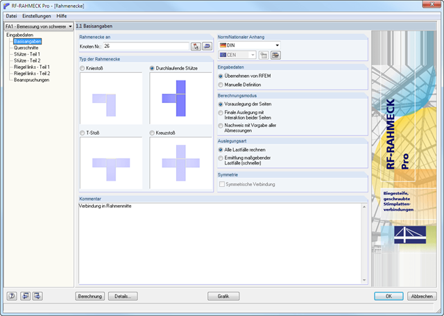
- Projektowanie połączeń kolanowych, teowych, krzyżowych i ciągłych połączeń słupów o przekrojach dwuteowych
- Import geometrii i danych obciążenia z programu RFEM/RSTAB lub ręczna specyfikacja połączenia (np. do ponownego obliczenia bez istniejącego modelu w RFEM/RSTAB)
- Połączenia zlicowane z górą lub połączenia z rzędem śrub w przedłużeniu
- Obliczanie dodatnich i ujemnych momentów w połączeniach ramy
- Różne kąty nachylenia prawych i lewych belek poziomych oraz zastosowanie w ramach dachów dwuspadowych i jednospadowych
- Uwzględnienie dodatkowych pasów w belce poziomej, na przykład w przypadku przekrojów o zbieżnym przekroju
- Symetryczne i asymetryczne połączenia teowe lub krzyżowe
- Dwustronne połączenie z różnymi wysokościami przekroju po prawej i lewej stronie
- Automatyczny wstępny projekt rozmieszczenia śrub i wymaganego usztywnienia
- Opcjonalny tryb obliczeń z możliwością definiowania wszystkich rozstawów śrub, spoin i grubości blachy
- Sprawdzenie zdolności do skręcania śrub z możliwością dostosowania wymiarów zastosowanych kluczy
- Klasyfikacja połączeń za pomocą sztywności i obliczanie sztywności sprężystej połączeń uwzględnianych przy określaniu sił wewnętrznych
- Sprawdź do 45 pojedynczych obliczeń (elementów) połączenia
- Automatyczne określanie decydujących sił wewnętrznych dla każdego obliczenia z osobna
- Możliwość wyświetlania grafiki połączeń w trybie renderowania ze specyfikacjami dotyczącymi materiału, grubości blachy, spoin, rozstawu śrub i wszystkich wymiarów konstrukcyjnych
- Zintegrowane i elastycznie rozszerzalne ustawienia załączników krajowych zgodnie z normą EN 1993-1-8
- Automatyczna konwersja sił wewnętrznych z analizy statyczno-wytrzymałościowej na odpowiednie przekroje, również w przypadku mimośrodowych połączeń prętów
- Automatyczne określanie sztywności początkowej Sj,ini połączenia
- Szczegółowa kontrola poprawności wszystkich wymiarów, wraz z podaniem wprowadzanych wartości granicznych (np. dla odległości od krawędzi i rozstawu otworów)
- Możliwość przyłożenia sił ściskających do słupa poprzez kontakt
- Możliwość aktualizacji wysokości przekroju belek poziomych w przypadku połączeń o zmiennym przekroju po zoptymalizowaniu geometrii połączenia w RF-/FRAME-JOINT Pro
Po zakończeniu obliczeń wszystkie wyniki są wyświetlane w przejrzyście ułożonych tabelach wyników; na przykład według przypadku obciążenia lub według węzła. Decydujące siły wewnętrzne są porównywane z wartościami granicznymi wymienionymi w wytycznych DSTV.
Połączenia można zwizualizować graficznie w module dodatkowym lub w programie RFEM/RSTAB. Oprócz danych wejściowych i wyników, w tym szczegółowych informacji dotyczących obliczeń, wyświetlanych w tabelach, do protokołu wydruku można dodać wszystkie grafiki. W ten sposób dokumentacja jest przejrzysta i zrozumiała.
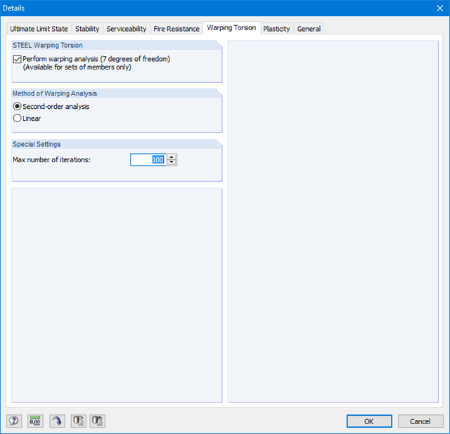
Ponieważ moduł RF-/STEEL Warping Torsion jest w pełni zintegrowany z modułami RF-/STEEL AISC i RF‑/STEEL EC3, dane są wprowadzane w taki sam sposób, jak w przypadku obliczeń w tych modułach. W oknie dialogowym Szczegóły, zakładka Skręcanie skrępowane (patrz rysunek po prawej stronie), konieczne jest tylko zaznaczenie opcji "Przeprowadzić analizę skręcania skrępowanego". W tym oknie dialogowym można również zdefiniować maksymalną liczbę iteracji.
Analiza skręcania skrępowanego jest przeprowadzana dla zbiorów prętów w modułach RF-/STEEL AISC i RF-/STEEL EC3. Można dla nich zdefiniować warunki brzegowe, takie jak podpory węzłowe lub zwolnienia na końcach prętów.
Możliwe jest również określenie imperfekcji do obliczeń nieliniowych.
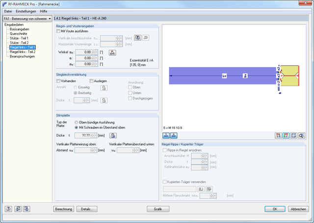
Moduł dodatkowy RF-/FRAME-JOINT Pro służy do wymiarowania połączeń konstrukcji, obliczonych w programie RFEM/RSTAB. Jeżeli konstrukcja w programie RFEM/RSTAB nie jest dostępna, geometrię i obciążenie można zdefiniować ręcznie; na przykład podczas sprawdzania obliczeń zewnętrznych.
W programie RFEM/RSTAB wybiera się węzeł do obliczenia. Moduł automatycznie rozpoznaje wszystkie połączone pręty i przydziela im typ połączenia. W zależności od typu połączenia, można zdefiniować dalsze szczegóły żeber, blach oporowych, blach środnika, śrub, spoin oraz rozstawu otworów. Jako obciążenia można wybrać dowolny przypadek obciążenia, kombinację obciążeń lub kombinację wyników w programie RFEM/RSTAB.
W przypadku pracy w trybie "obliczeń wstępnych", RF-/FRAME-JOINT Pro przeprowadza pierwszy krok obliczeń, aby zasugerować odpowiednie ułożenia. Po wybraniu odpowiedniego układu moduł wyświetla wszystkie obliczenia w szczegółowych tabelach wyników i grafice.
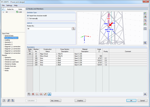
Węzły połączenia można wybierać graficznie w modelu programu RFEM/RSTAB. Odpowiednie dane przekroju i geometria są importowane automatycznie. Parametry połączeń profili rurowych można również zdefiniować ręcznie. W razie potrzeby przekroje można modyfikować w module.
Domyślny kąt między krzyżulcami a pasami można również zmienić. Geometryczny stosunek krzyżulców do siebie jest ważny dla prawidłowego wyboru obliczeń. Zależność tę można zdefiniować poprzez określenie odstępu między zastrzałami lub poprzez ich zachodzenie na siebie.
Obszerne wytyczne DSTV znajdują się w specjalnej bazie danych zintegrowanej w module DSTV. Każde połączenie jest opisane niepowtarzalnym kodem alfanumerycznym.
Możliwe połączenia DSTV można odfiltrować na podstawie odpowiednich ustawień dla typu połączenia DSTV (IH, IW, IS, IG oraz IK) oraz zastosowanego przekroju. W ten sposób można określić nośność wybranego połączenia.
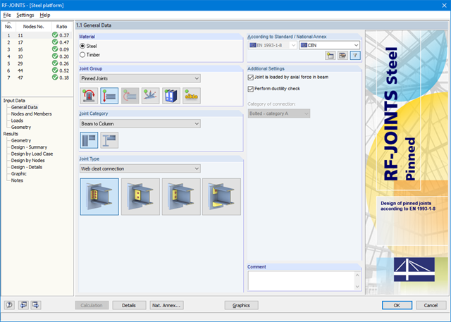
Po otwarciu modułu należy wybrać grupę połączeń (Połączenia przegubowe), następnie kategorię oraz typ połączenia (środnik nakładkowy, blacha zakładkowa, blacha czołowa, blacha czołowa z podkładką). Następnie można wybrać węzły do obliczeń w modelu RFEM/RSTAB. RF-/JOINTS Steel - Pinned automatycznie rozpoznaje pręty połączenia i określa na podstawie ich położenia, czy są to słupy czy belki.
W razie potrzeby można wyłączyć określone pręty z obliczeń. Konstrukcyjnie podobne połączenia można projektować jednocześnie dla kilku węzłów. Obciążenia wymagają wyboru miarodajnych przypadków obciążeń, kombinacji obciążeń lub kombinacji wyników. Alternatywnie można ręcznie wprowadzić przekrój i obciążenie. W ostatnim oknie wprowadzania danych połączenie jest konfigurowane krok po kroku.
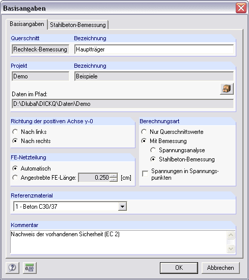
Przekrój można dowolnie modelować przy użyciu powierzchni ograniczonych liniami wielokątów, wraz z otworami i powierzchniami punktowymi (pręty zbrojeniowe). Oprócz tego można zaimportować geometrię przy użyciu interfejsu DXF. Obszerna biblioteka materiałów ułatwia modelowanie przekrojów złożonych.
Stopniowanie zbrojenia można uwzględnić przy użyciu średnic granicznych i priorytetów. Ponadto można uwzględnić odpowiednie otuliny betonowe oraz sprężenie.
- Iteracyjne nieliniowe obliczanie deformacji dla konstrukcji belkowych i płytowych wykonanych z betonu zbrojonego poprzez określenie sztywności odpowiedniego elementu poddanego zdefiniowanym obciążeniom
- Analiza deformacji zarysowanych powierzchni żelbetowych (stan II)
- Ogólna nieliniowa analiza stateczności prętów ściskanych wykonanych z betonu zbrojonego; na przykład zgodnie z EN 1992-1-1, 5.8.6
- Usztywnienie przy rozciąganiu betonu między rysami
- Dostępne są liczne załączniki krajowe do obliczeń zgodnie z Eurokodem 2 (EN 1992-1-1:2004 + A1:2014, patrz EC2 dla RFEM)
- Opcjonalne uwzględnienie wpływów długotrwałych, takich jak pełzanie lub skurcz
- Nieliniowe obliczanie naprężeń w stali zbrojeniowej i betonie
- Nieliniowe obliczanie szerokości rys
- Elastyczność dzięki szczegółowym opcjom ustawień dla podstawy i zakresu obliczeń
- Graficzne przedstawienie wyników zintegrowane z RFEM; na przykład odkształcenie lub ugięcie płaskiej płyty wykonanej z betonu zbrojonego
- Przejrzyste zestawienie wyników w formie numerycznej w stosownych oknach oraz możliwość ich graficznego przedstawienia na konstrukcji
- Pełna integracja wyników z protokołem wydruku programu RFEM
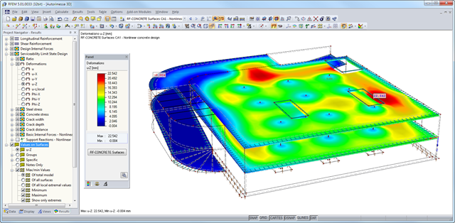
Po zakończeniu obliczeń, moduł wyświetla przejrzyście ułożone tabele zawierające wyniki obliczeń nieliniowych. Wszystkie wartości pośrednie są uwzględnione w sposób zrozumiały. Graficzne przedstawienie stopni wykorzystania, odkształceń, naprężeń w betonie i stali zbrojeniowej, szerokości i głębokości rys oraz odległości między rysami w programie RFEM ułatwia szybki przegląd obszarów krytycznych lub zarysowanych.
Komunikaty o błędach lub uwagi dotyczące obliczeń ułatwiają znajdowanie problemów obliczeniowych. Ponieważ wyniki obliczeń są wyświetlane według powierzchni lub punktów wraz ze wszystkimi wynikami pośrednimi, można odtworzyć wszystkie szczegóły obliczeń.
Dzięki opcjonalnemu eksportowi tabel danych wejściowych lub wyników do MS Excel, dane pozostają dostępne do wykorzystania w innych programach. Pełne zintegrowanie wyników z protokołem wydruku programu RFEM gwarantuje weryfikowalność wymiarowania konstrukcji.
RF-CONCRETE Surfaces (en)
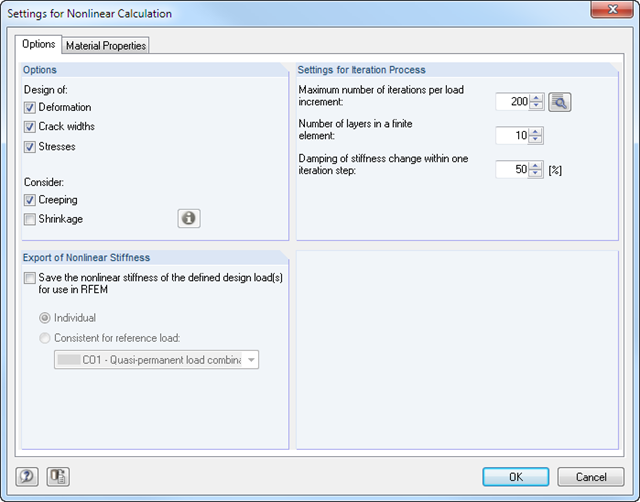
Obliczenia nieliniowe rozpoczyna się poprzez wybranie tej metody dla obliczeń w stanie granicznym użytkowalności. Różne typy analizy, a także wykresy odkształceń i naprężeń dla betonu oraz stali zbrojeniowej można wybrać indywidualnie. Na proces iteracji mogą mieć wpływ następujące parametry kontrolne: dokładność zbieżności, maksymalna liczba iteracji, rozmieszczenie warstw na wysokości przekroju oraz współczynnik tłumienia.
Wartości graniczne w stanie granicznym użytkowalności można ustawić indywidualnie dla każdej powierzchni lub grupy powierzchni. Jako dozwolone wartości graniczne można zdefiniować deformację maksymalną, naprężenia maksymalne oraz maksymalne szerokości rys. Podczas definiowania deformacji maksymalnej należy dodatkowo określić, czy do obliczeń ma zostać użyty układ odkształcony czy nieodkształcony.
RF-CONCRETE Members (en)
Obliczenia nieliniowe można zastosować do obliczeń stanu granicznego nośności i użytkowalności. Użytkownik może indywidualnie ustalać, w jaki sposób stosowane są wytrzymałość betonu na rozciąganie lub usztywnienie przy rozciąganiu. Na proces iteracji mogą wpływać następujące parametry kontrolne: dokładność zbieżności, maksymalna liczba iteracji i współczynnik tłumienia.
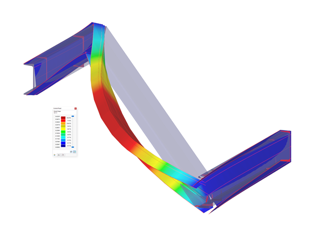
- Model połączeń stalowych i wyniki można zapisać jako osobny plik modelu
- Uzyskane naprężenia i wyniki analizy stateczności (wyboczenia połączenia) można wyświetlić w osobnym modelu
- W zapisanym modelu można uruchomić animację deformacji połączenia
- Elementy połączenia są podczas zapisywania przekształcane w powierzchnie i pręty
RF-CONCRETE Surfaces:
Nieliniowa analiza deformacji jest przeprowadzana metodą iteracyjną, z uwzględnieniem sztywności w przekrojach zarysowanych i niezarysowanych. Nieliniowe modelowanie betonu zbrojonego wymaga zdefiniowania właściwości materiału, które różnią się w zależności od grubości powierzchni. Dlatego element skończony jest dzielony na określoną liczbę warstw stali i betonu w celu określenia wysokości przekroju.
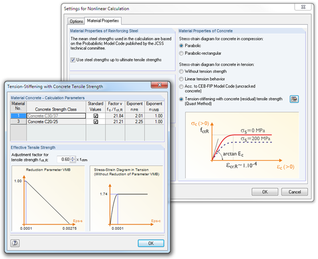
Średnie wytrzymałości stali zastosowane w obliczeniach oparte są na 'Normie modelu probabilistycznego', opublikowanym przez komitet techniczny JCSS. To od użytkownika zależy, czy wytrzymałość stali zostanie przyłożona do granicy wytrzymałości na rozciąganie (wzrost rozgałęzienia w obszarze plastycznym). W odniesieniu do właściwości materiałowych można kontrolować wykres naprężenie-odkształcenie dla wytrzymałości na ściskanie i rozciąganie. Jako wytrzymałość betonu na ściskanie można wybrać paraboliczny lub paraboliczno-prostokątny wykres naprężenie-odkształcenie. Po stronie rozciągania betonu istnieje możliwość dezaktywacji wytrzymałości na rozciąganie, a także zastosowania wykresu liniowo-sprężystego, wykresu zgodnie z normą modelu CEB-FIB 90:1993 oraz rezydualnej wytrzymałości betonu na rozciąganie z uwzględnieniem usztywnienia rozciąganego między rysami.
Ponadto można określić, które wartości wyników mają być wyświetlane po obliczeniach nieliniowych w stanie granicznym użytkowalności:
- Odkształcenia (globalne, lokalne dla układu niezdeformowanego/nieodkształconego)
- Szerokości, wysokości rys oraz rozstaw górnej i dolnej powierzchni w głównych kierunkach I oraz II
- Naprężenia w betonie (naprężenie i odkształcenie w głównym kierunku I i II) oraz w zbrojeniu (odkształcenie, pole przekroju, profil, otulina i kierunek w każdym kierunku zbrojenia)
RF-CONCRETE Members:
Nieliniowa analiza deformacji konstrukcji szkieletowych jest przeprowadzana metodą iteracyjną, uwzględniającą sztywność w przekrojach zarysowanych i niezarysowanych. Właściwości materiałowe betonu i stali zbrojeniowej wykorzystywane w obliczeniach nieliniowych są wybierane zgodnie ze stanem granicznym. Udział wytrzymałości betonu na rozciąganie pomiędzy rysami (wzmocnienie przy rozciąganiu) można określić za pomocą zmodyfikowanego wykresu naprężenie-odkształcenie stali zbrojeniowej lub poprzez zastosowanie rezydualnej wytrzymałości betonu na rozciąganie.