Nelineární metoda posouzení
Pro posouzení nelineární metodou je zapotřebí licence k přídavnému modulu RF-CONCRETE NL. Tento postup je popsán v kapitole 2.8. Provede se fyzikální a geometrický nelineární výpočet.
Upozornění
Nelineární postup posouzení vychází z interakce mezi modelem a namáháním, které vyžaduje jednoznačné rozdělení vnitřních sil. Proto lze posuzovat pouze zatěžovací stavy a kombinace zatížení, nikoli však kombinace výsledků (KV). V kombinaci výsledků jsou pro každý uzel sítě KP k dispozici dvě hodnoty - maximální a minimální.
Vnitřní síly pro nelineární posouzení se zpravidla stanoví podle teorie druhého řádu.
Tlačítko [Otevřít dialog] otevře dialog, v němž můžeme zkontrolovat a případně upravit parametry posouzení. Tento dialog je rozdělen do záložek Možnosti a Materiálové charakteristiky.
![]()
Nástroje
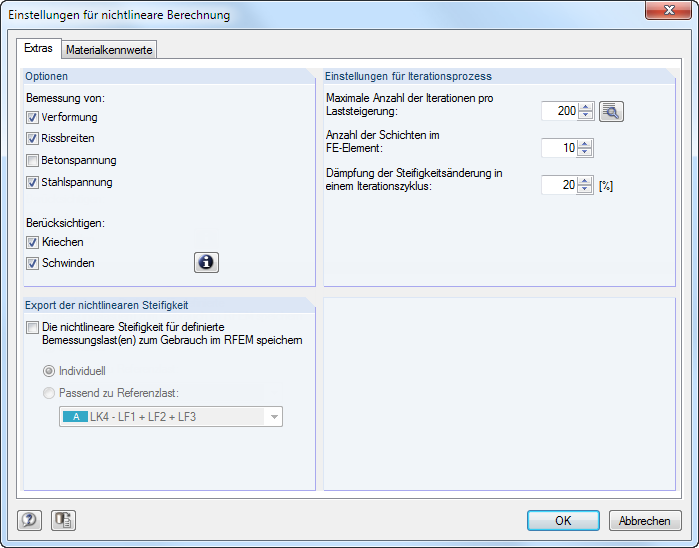
Možnosti
V této sekci lze určit, která posouzení se mají provést v mezním stavu použitelnosti:deformace, šířky trhlin a také napětí v betonu a oceli.Musí být zaškrtnuto alespoň jedno ze čtyř zaškrtávacích políček.
Můžete také rozhodnout, zda se má při nelineárním výpočtu zohlednit vliv dotvarování a smršťování.
Podrobná nastavení pro jednotlivá posouzení a také pro dotvarování a smršťování se provádí v dialogu 1.3 Plochy (viz kapitola 3.3.2).
Export nelineární tuhosti
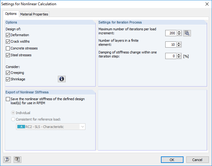
Nastavení v této sekci mají vliv na průběh nelineární metody posouzení. Další informace najdete v kapitole 2.8.2.4.
![]()
Při úpravě přesnosti iterací je třeba dbát na to, aby Maximální počet iterací byl vyšší než bod v procesu výpočtu, od kterého se navíc zohledňuje kritérium deformace. Po kliknutí na tlačítko [Detaily] v programu RFEM se otevře dialog Parametry výpočtu. V něm lze upravit přesnost kritérií konvergence pro nelineární výpočet.
Při nelineárním výpočtu se plocha rozdělí na takzvané vrstvy (viz kapitola 2.8.2.1). Doporučený počet vrstev je 10.
Kromě toho lze konvergenční chování ovlivnit pomocí funkce Tlumení: Tlumení řídí velikost změny tuhosti v následujících krocích výpočtu. Pokud například zadáte tlumení 50 %, může změna tuhosti mezi krokem 2 a 3 činit maximálně 50 % změny tuhosti mezi krokem 1 a 2.
Materiálové charakteristiky
Materiálové charakteristiky výztuže
Pomocí zaškrtávacího políčka lze určit, zda se má výpočet v plastické oblasti pracovního diagramu betonářské výztuže provádět pomocí vzestupného nebo vodorovného průběhu (viz kapitola 2.8.3.4).
Materiálové charakteristiky betonu
V této sekci lze zadat pracovní diagramy betonu v tlaku a v tahu. Přednastaven je parabolický diagram pro tlakové a tahové zpevnění pro tahová napětí betonu.
![]()
Pro tahové zpevnění (zohlednění ztužujícího účinku betonu v tažené oblasti) lze v samostatném dialogu zadat parametry, které se použijí pro stanovení pevnosti betonu v tahu mezi trhlinami. Pro otevření klikněte na tlačítko [Upravit].
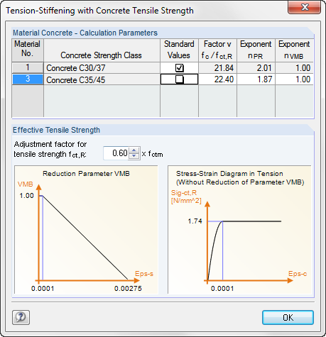
Změny parametrů se okamžitě zobrazí graficky v diagramech.
Použití Tahového zpevnění je popsáno v kapitole 2.8.3.3.