Návrhové momenty
The internal forces interpolated from the FE nodes can be found in the design details of the grid point. As the model type 3D was specified in the general data (see Figure 2.1), the moments mx, my, and mxy, as well as the axial forces nx, ny, and nxy exist in the surface.

The principal internal forces are determined from the RFEM internal forces of the linear analysis. They are determined according to the equations described in chapter 2.3 and chapter 2.4.
- Online manuál | RF-CONCRETE Surfaces | 2 Teoretické základy | 2.3 Stěny (diafragmata)
- Online manuál RFEM 5 | RF-CONCRETE Surfaces | 2 Teoretické základy | 2.4 Desky
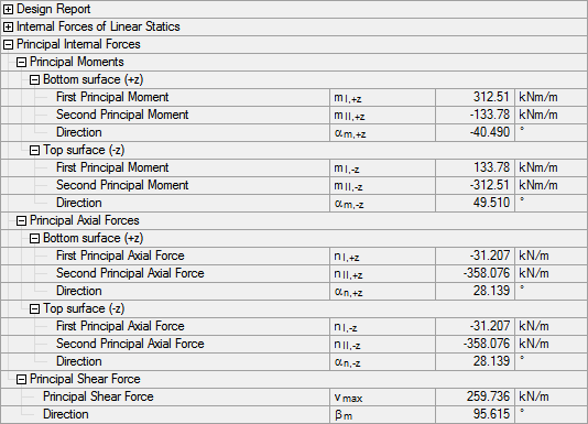
For shells, the principal axial forces are shown for both plate sides because they are required for the design as a shell. Unlike the moments, the principal axial forces at the bottom and top surface of the plate are the same.
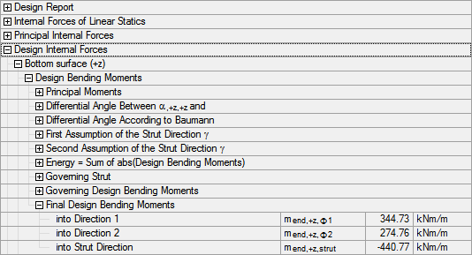
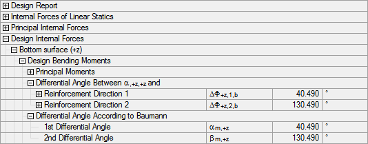
The design moments are now determined from the principal moments mI,+z and mII,+z at the bottom side of the surface. For this purpose, the program first determines the differential angles αm,+z and βm,+z between the direction γm,+z of the first principal axial force mI,+z at the surface's bottom side and the two reinforcement directions φ1 = 0° and φ2 = 90°.
Now we search for the direction of a moment that stiffens the two-directional reinforcement mesh. As previously shown for walls and plates, only the two angles between the directions of the reinforcement sets qualify as moment directions. The analysis for the surface's bottom side yields these directions for the assumed concrete compression struts:
Only the assumption of the direction γm,+z,1 of 85.490° proves to be valid. Since no optimization of this angle is carried out anymore, the final design moments mend,+z,φ1 and mend,+z,φ2 are obtained in the direction of both reinforcement sets: