Frame Girder
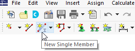
To define the frame girder graphically, click the
![]() button on the toolbar.
button on the toolbar.
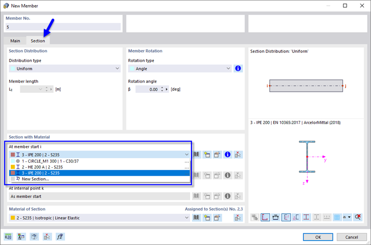
The 'New Member' dialog box opens.
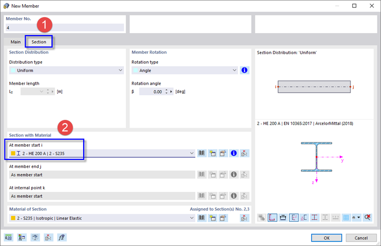
Click the Section tab (1) and select the HE 200 A section from the list as before (2). Then click OK.
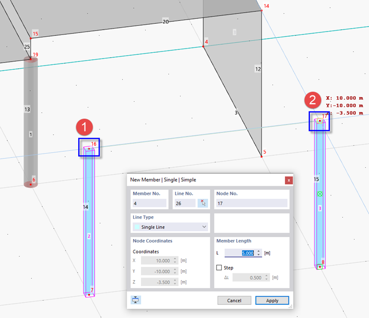
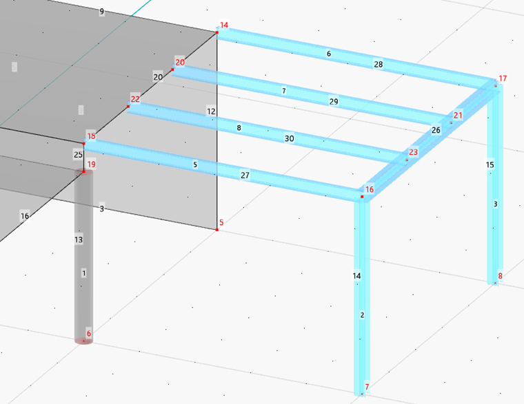
Click the two top nodes of the steel columns (no. 16 and 17) one after another. Then click Cancel (or right-click) to quit the function.
Grid Girders
The frame is connected to the concrete surfaces by four platform girders. Click the
![]() button once again. In the 'New Member' dialog box, select the Section tab as before.
button once again. In the 'New Member' dialog box, select the Section tab as before.
Select the IPE 200 section from the list and then click OK.
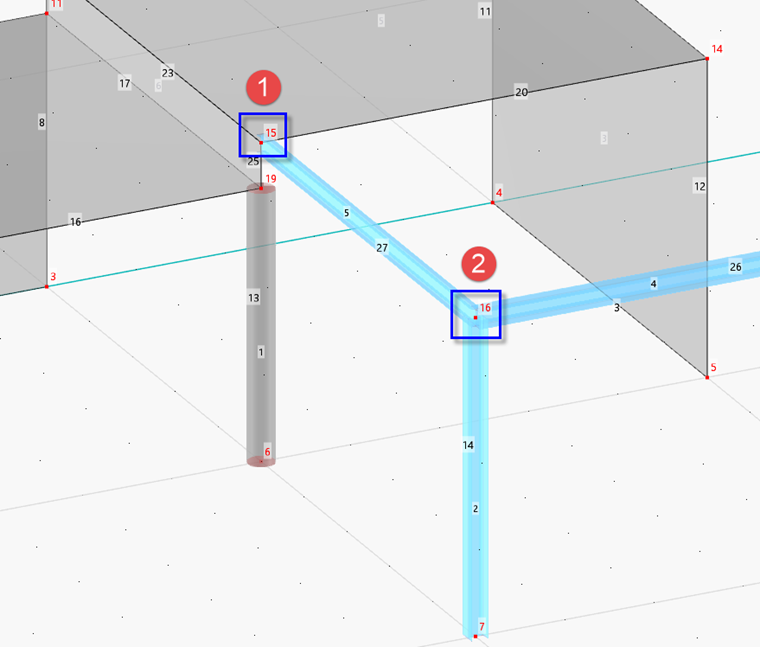
Now click the nodes no. 15 and 16 one after another.
Click Cancel again.
Copying Member Graphically
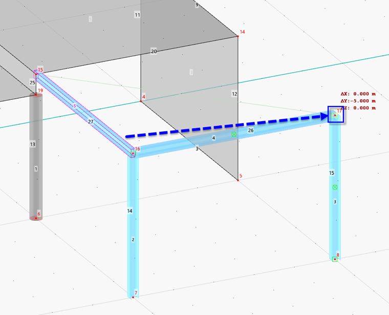
Press the Ctrl key and hold it down. Grab the new member (no. 5) anywhere in its half that is connected to the steel column and drag it to node no. 17 – the opposite end of the platform. When the coordinates of this node are shown next to the pointer, release the mouse key.
Copying Member by Menu Function
Right-click the new member (no. 6) to open its shortcut menu.

Select the Manipulation → Move/Copy option.

In the 'Move/Copy' dialog box, select the Create copy option and enter 2 copies. Then enter the 'Displacement vector' which is 5 m / 3 = 1.667 m in Y-direction and 0.000 m in Z-direction.
Go to the Numbering & Options tab.
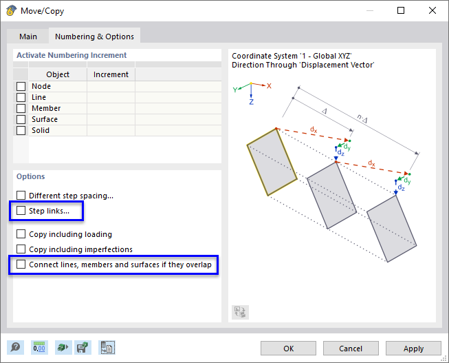
Clear the Link steps and Connect lines, members and surfaces if they overlap check boxes so that the lines of the slab and the frame girder are not split up. This will be relevant when designing the members later. Finally, click OK.