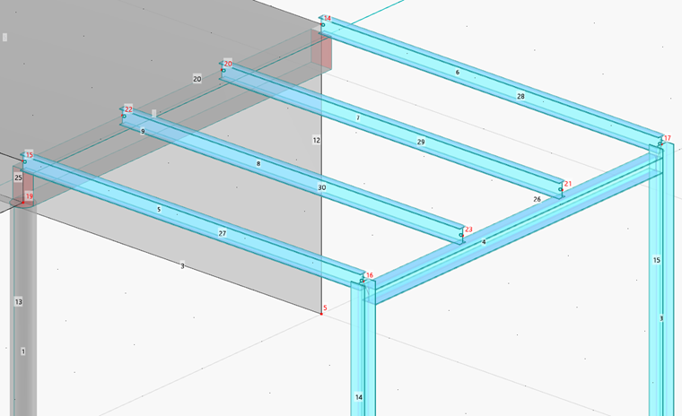
The steel beams are connected at the intersections of their centroidal axes, which represents the structural model. In the 3D rendering, however, this type of connection does not really represent the reality. To improve the graphical display in an exemplary fashion, the frame girder is to be set beneath the platform beams and aligned with the columns. This offset will also have an effect on the internal forces.
Double-click the frame girder (member no. 4). In the "Edit Member" dialog box, select the Eccentricities option (beneath the "Hinges" option; see the Edit Members image). Then, select the Eccentricities tab.
Click the
![]() button to define a new type of eccentricity (1).
button to define a new type of eccentricity (1).
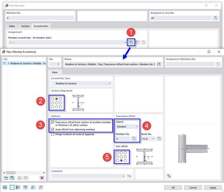
When the eccentricity is related to another section, the program sets the values of the offsets automatically.
In the "Section Alignment" area, select the top center
![]() option (2) to align the frame girder at the center of its upper flange with the connected object. Then, select the Transverse offset from section of another member and the Axial offset from adjoining member in the "Options" area (3).
option (2) to align the frame girder at the center of its upper flange with the connected object. Then, select the Transverse offset from section of another member and the Axial offset from adjoining member in the "Options" area (3).
In the "Transverse Offset" area, select one of the platform members graphically – for example, no. 5 – by using the
![]() button (4). As the frame girder is to be set under the connected objects, select the bottom center
button (4). As the frame girder is to be set under the connected objects, select the bottom center
![]() option next to the section sketch (5). Then, click OK.
option next to the section sketch (5). Then, click OK.
To allocate this eccentricity to the other member end as well, open the list below "At member end j" as before. Select the eccentricity type no. 1.
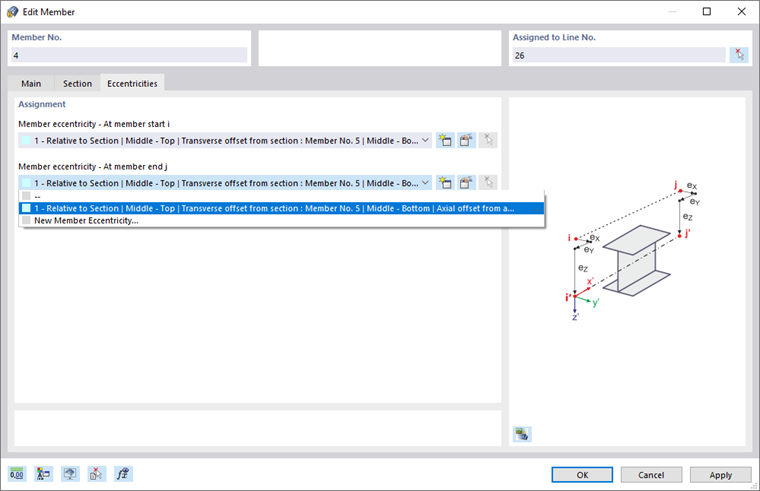
Click OK to allocate the eccentricities.
This type of eccentricity is sufficient for the tutorial model. In a similar manner, it is possible to define an axial offset of the platform girders towards the downstand beam.
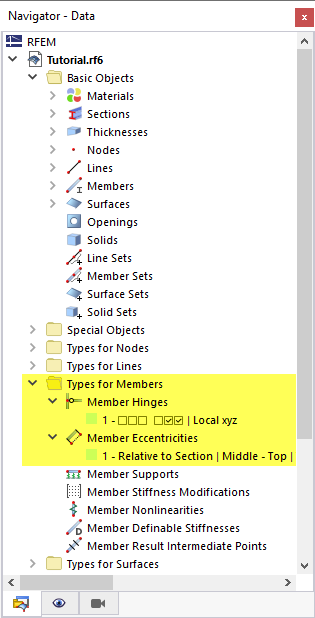
In the navigator tree, all hinges and eccentricities are listed in the "Types for Members" folder.