Home Downloads & Info References Customer Projects Open-Air Theater Grandstand Roof Structure in Sömmersdorf, Germany
Open-Air Theater Grandstand Roof Structure in Sömmersdorf, Germany
Customer Project
06/25/2019
001137
An impressive roof structure was constructed over the Passion Play open-air theater in Sömmersdorf, Franconia (Germany). The self-supporting spatial steel structure includes a PVC membrane roof covering the 14,908 ft² auditorium. Only four foundations in total support the entire roof structure.
Client |
Fränkische Passionsspiele Sömmersdorf passionsspiele-soemmersdorf.de |
Architect |
Dipl.-Ing (FH) Michael Theiss, Oberwerrn www.michaeltheiss.de |
Structural Analysis |
Joachim Ingenieure, Schweinfurt Dipl.-Ing. (FH) Stephan Knop www.joachim-ing.de |
- Length: ~ 131 ft
- Width: ~ 148 ft
- Height: ~ 39 ft
- Number of Nodes: 2620
- Number of Members: 4620
- Cross-Sections: 31
Model
The valuable Dlubal customer Joachim Ingenieure was the design engineer for this fascinating project. The engineering office utilized RSTAB for the structural analysis.
Structure
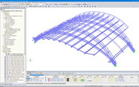
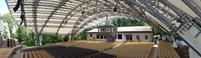
The main structure includes two pairs of framework arched trusses inclined in opposite transverse directions. The trusses have a free span close to 148 ft. Twelve additional trusses span between the main arched truss pairs in the longitudinal direction. They also cantilever 26 ft at the end locations. The total length of the roof structure amounts to 131 ft.
The arched trusses as well as the intermediate trusses consist almost exclusively of circular tube sections. The roof’s transverse stiffness is provided by the arched trusses while the longitudinal stifness is provided by the intermediate trusses as well as X-braces.
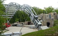
The four abutments constructed at a 45° angle are fixed to the ground with a reinforced concrete foundation including micropiles with varying angles. The micropiles for one abutment measure a total length of 433 ft.
Project Location
Contact us
Do you have questions or need advice?
Contact our free e-mail, chat, or forum support or find various suggested solutions and useful tips on our FAQ page.
Recommended Events
Eurocode 3 | Steel structures according to DIN EN 1993-1-1
Online Training 05/06/2021 8:30 AM - 12:30 PM CEST
Designing Cold-Formed Steel Sections According to Eurocode 3
Webinar 04/30/2020 3:00 PM - 3:45 PM CEST
Membrane Structures with Wind Loads from CFD Wind Simulation
Webinar 03/24/2020 3:00 PM - 4:15 PM CET
Videos
Models to Download
Knowledge Base Articles

New
Not all structural elements of a real building are included in a structural model. As an example, we can look at a pipe that runs along a steel girder frame.Screenshots
RF-/PLATE-BUCKLING Add-on Module for RFEM/RSTAB | Plate Buckling Analysis for Plates with or Without Stiffeners According to 1993-1-5
RFEM/RSTAB Add-on Module RF-IMP/RSIMP | Generation of Geometric Replacement Imperfections and Pre-deformed Replacement Structures
Extension of the RF-/STEEL Warping Erosion module | Lateral -torsional buckling analyzes of members according to the second -order theory with 7 degrees of freedom
RFEM/RSTAB add-on module RF-/TOWER effective lengths | Determination of effective lengths of lattice towers
RFEM/RSTAB add-on module RF-/JOINTS Steel-Column Base | Hinged and restrained column bases according to EC 3
RFEM/RSTAB add-on module RF-/STEEL BS | Design of steel members according to BS 5950 or BS EN 1993-1-1
Product Features Articles

SHAPE-THIN determines the effective cross-sections according to EN 1993-1-3 and EN 1993-1-5 for cold-formed sections. You can optionally check the geometric conditions for the applicability of the standard specified in EN 1993‑1‑3, Section 5.2.
The effects of local plate buckling are considered according to the method of reduced widths and the possible buckling of stiffeners (instability) is considered for stiffened sections according to EN 1993-1-3, Section 5.5.
As an option, you can perform an iterative calculation to optimize the effective cross-section.
You can display the effective cross-sections graphically.
Read more about designing cold-formed sections with SHAPE-THIN and RF-/STEEL Cold-Formed Sections in this technical article: Design of a Thin-Walled, Cold-Formed C-Section According to EN 1993-1-3.
Frequently Asked Questions (FAQ)
- I am trying to manually check the deformations from the CRANEWAY add-on module. However, I obtain great deviations. How to explain the differences?
- What should be considered when using a failure of columns under tension in the RF‑/DYNAM Pro – Equivalent Loads add-on module?
- Why is there no stability analysis displayed in the results despite the activation of the stability analysis in RF‑/STEEL EC3?
- How can I model and design a crane runway girder with Dlubal Software?
- How do I model a suspended membrane roof structure with line supports?
- Is it possible to set user-defined values when viewing solid stress results?
- How do I model a tent roof with two cone tips?
- Why do I get large differences for the design of a longitudinally stiffened buckling panel in comparison with the German and Austrian National Annex?
- How are the signs for the release results of a line release and line hinges interpreted?
- How can I create a curved or arched section?
Customer Projects
Programs Used for Structural Analysis