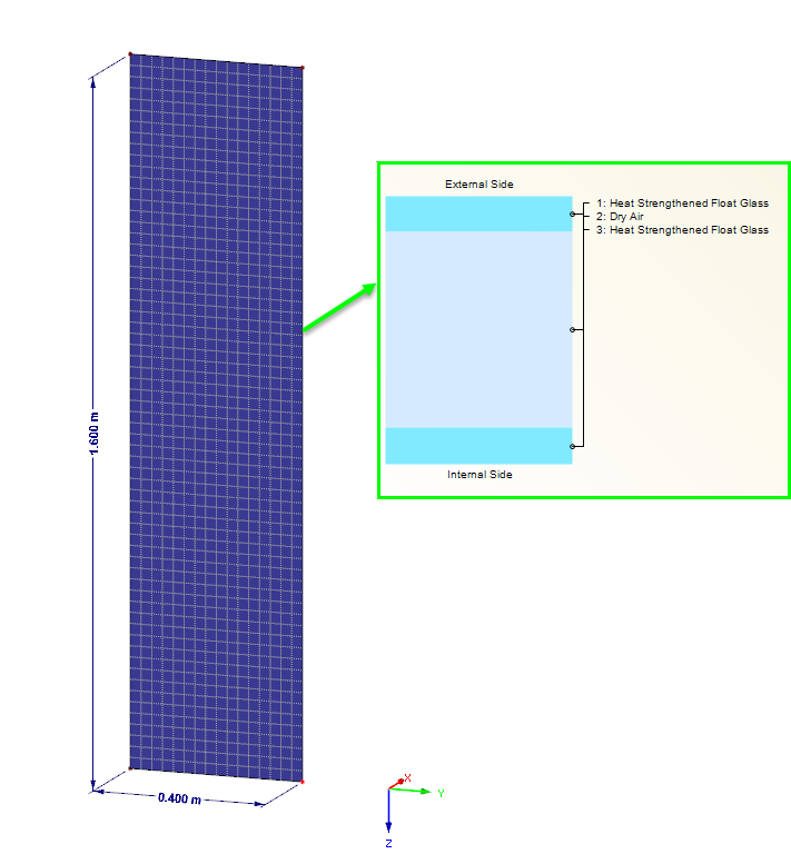
System Basis
A vertical glass pane with a height of h = 1,600 mm and a width of b = 400 mm is examined. The pane is supported by restrained supports on four sides for the horizontal loads as well as by singular supports for the vertical loads. The insulated glass pane with double glazing consists of two edge panes of 3.0 mm each, and a space between panes of 16.0 mm. The examined effect is considered as the "Summer" climatic load case in compliance with DIN 18008-1 [1].
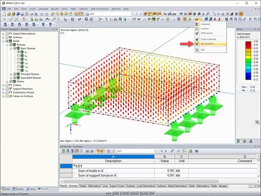
Check of Resulting Gas Pressure
The relationship between the deformation and the resulting pressure in the space between panes can be determined using the general gas equation.
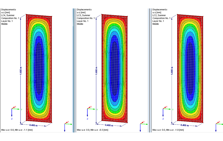
Due to the deformations calculated in the finite element analysis, there is a change in the gas volume. If these are applied to the system, the following values are obtained:
- Load Case 2, temperature difference: ΔV = 645.13 cm³
- Load Case 3, atmospheric pressure difference: ΔV = 186.99 cm³
- Load Case 4, local altitude difference: ΔV = 704.16 cm³
Using the initial volume and the temperature change, we can now calculate the resulting gas pressure.
The following values are used:
- p1 = 103 kN/m²
- V1 = 10,240 cm³
- T1 = 292 K
- T2 = 312 K (Load Case 2)
- T2 = T1 = 292 K (Load Case 3 + 4)
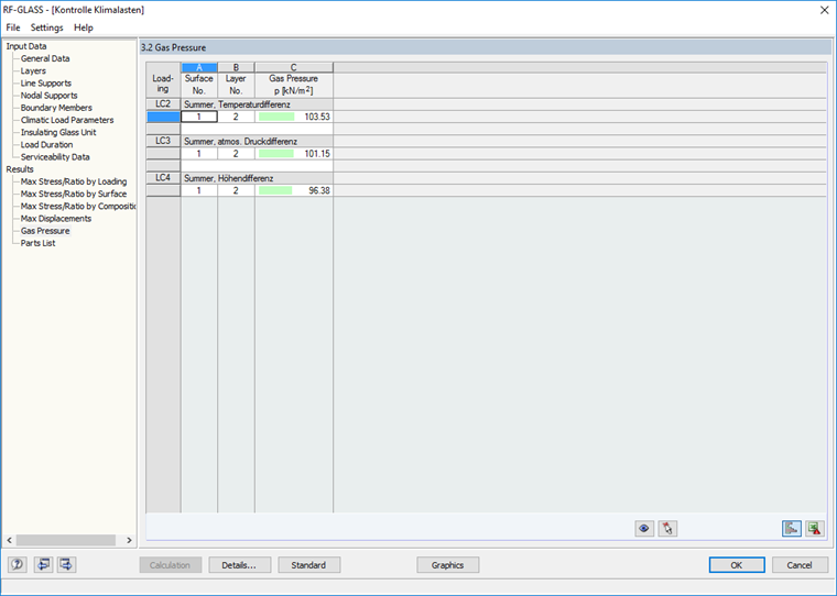
Thus, the following results are obtained:
- Load Case 2: p2 = 103.53 kN/m²
- Load Case 3: p2 = 101.15 kN/m²
- Load Case 4: p2 = 96.37 kN/m²
In comparison with the FE analysis performed in RFEM, this gives exactly the same values.
Check Using Applied Surface Load
When comparing the applied load on the entire system with a surface system, the most difficult thing is to convert the surface load to be applied according to DIN 18008‑1 to the surface system. However, such cases are documented in technical literature (in [2], for example), so you can always find help there.
Based on the dimensions of the glass pane and the glass layer structure, the insulating glass factor is calculated. Thus, you can determine the load distribution in both panes.
The following parameters are taken into account:
Load Case of Temperature Difference
In the climatic load case of the temperature difference (summer), a temperature change of 20°C is applied. The internal and external pressures are 1.03 bar. This results in a load of q = 0.34 ∙ ΔT = 6.8 kN/m² and a load on the single pane of q = 6.8 ∙ 0.0754 = 0.513 kN/m².
It is now possible to perform a "manual" design based on the surface load on the single pane. However, this is not further pursued in this article.
This surface load can be used to determine the relation between the load and the resulting gas pressure:
pend,in = 103.0 kN/m² + 0.513 kN/m² = 103.513 kN/m²
Load Case of Atmospheric Pressure Difference
The atmospheric pressure difference is specified by a pressure difference of 0.02 bar. This results in a load of q = 103.0 − 101.0 = 2.0 kN/m² on the entire system. The load on a single pane with the same dimensions is therefore q = 2.0 ∙ 0.0754 = 0.151 kN/m².
The resulting gas pressure in the space between the panes also results from the sum of the final pressure and the applied surface load:
pend,in = 101.0 kN/m² + 0.151 kN/m² = 101.151 kN/m²
Load Case of Altitude Difference
In the load case of the altitude difference, the difference of the local altitude of 600 m is applied by default. The resulting load is thus calculated as follows: q = 0.012 ∙ 600 = 7.2 kN/m². This is converted to the single system as follows: q = 7.2 ∙ 0.0754 = 0.543 kN/m².
Assuming that the atmospheric pressure at the installation site is about 7.2 kN/m² lower than at the production site, the resulting gas pressure in the space between the panes can also be calculated as follows:
pend,in = (103.0 kN/m² - 7.2 kN/m²) + 0.543 = 96.343 kN/m²
Conclusion
The comparative calculation has shown that the results of the nonlinear FEM calculation are very similar to the calculation using analytical formulas. The described procedure shows a simple verification of the global computer-aided calculation. Furthermore, this article has tried to clarify the relations between the loads on the glass pane and the pressure conditions in the space between the panes.
You can also verify the deformations and stresses using the loads calculated above. In this case, it should be noted that the computational calculation is usually based on the nonlinear, large deformation analysis where the analytical formulas were developed according to the linear static analysis. Therefore, there might be small differences in the results.


Dlubal_KohlA_]_LI.jpg?mw=350&hash=ee8d38f1c4853d80307fa156c159b5e78a3fdca9)