


The global settings of the concrete design as defined in Chapter Concrete Design Settings apply to all surfaces and members consisting of concrete. Therefore, it is not required to activate the design of the downstand beam and the column separately: The 'Concrete Design' is already enabled (see the Activating 'Concrete Design' Add-on image).
For the concrete design, 'EN 1992' was defined as standard (see the Selecting Standard and National Annex image). The ULS design situation 'DS5' based on the results of a geometrically linear analysis is also valid for the member elements (see the DS5 with Concrete Design Settings image).
The serviceability limit state design was disabled for all concrete objects (see the Deactivating 'Serviceability' Design image) as they are not to be treated in this tutorial.
Concrete Design of Members
All members were deactivated for the concrete design so that the surfaces could be analysed without any errors concerning undefined settings of the members (see the Selecting Object Types for Design image). To enable the design of the members now, select the Input Data category from the list in the 'Concrete Design' tables (1).
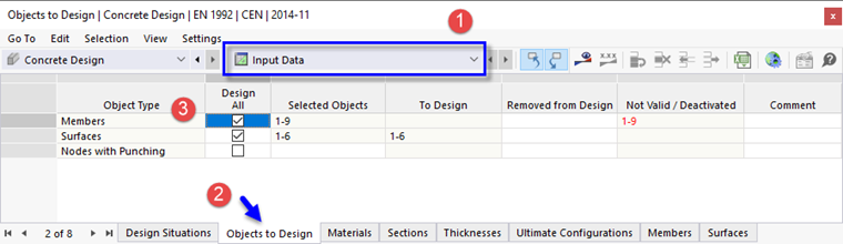
Go to the Objects to Design table (2). Then select the Design All check box of the 'Members' (3). Click Yes to confirm the question whether the concrete design results are to be deleted.
The 'To Design' column of the members is still empty as the parameters are not yet defined. Later, the 'Not Valid / Deactivated' column will show only the numbers of the steel members that are disabled automatically for the design (see the Starting Design image).
Design Configuration for Members
Two design configurations have been defined for the design of the surfaces (see the Ultimate Configuration for Walls image).
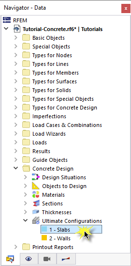
Set the Navigator - Data by clicking the
![]() tab. Then double-click the 1 - Slabs item of the 'Ultimate Configurations' category in the 'Concrete Design' folder. In the 'Edit Ultimate Configuration' dialog box, the new Members tab is shown.
tab. Then double-click the 1 - Slabs item of the 'Ultimate Configurations' category in the 'Concrete Design' folder. In the 'Edit Ultimate Configuration' dialog box, the new Members tab is shown.
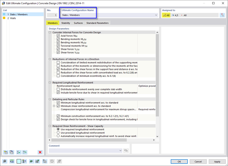
The 'Assigned to' area shows that all members are managed by this design situation. Therefore, add / Members in the 'Ultimate Configuration Name' area. It is not required to distinguish between the settings for ribs and columns. The default settings are suitable for both.
Close the dialog box by clicking OK.