


Defining the Surface Reinforcement
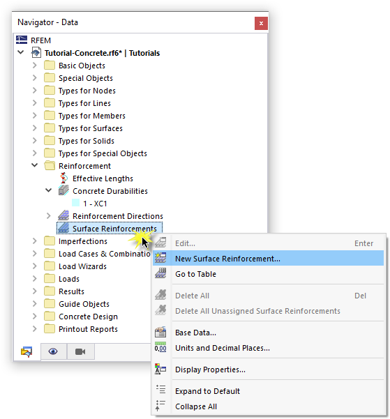
To define the reinforcement of the slabs, right-click the 'Surface Reinforcements' folder in the navigator. Then select New Surface Reinforcement in the shortcut menu.
The reinforcement consists of rebars 10 mm in diameter by default.
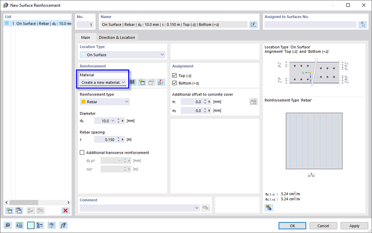
As no material has been defined for the reinforcing steel yet, select the Create a new material box in the 'Reinforcement' area. The 'New Material' dialog box opens.
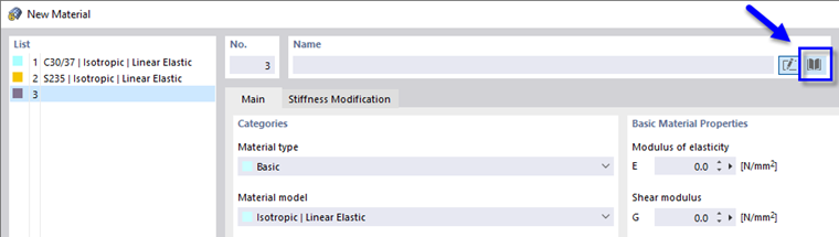
To define a new material using the library, click the
![]() button in the 'Name' area. In the 'Select Material from Library' dialog box, the 'Reinforcing Steel' material type is preset.
button in the 'Name' area. In the 'Select Material from Library' dialog box, the 'Reinforcing Steel' material type is preset.
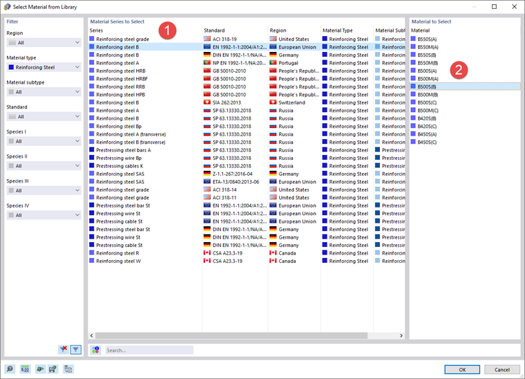
Click the Reinforcing steel B line in the 'Material Series to Select' area (1). Then select the B500S(B) steel grade in the 'Material to Select' area (2). When you click OK, you return to the 'New Material' dialog box where you can check the material properties.
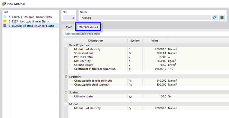
The Material Values tab manages all parameters relevant to the concrete design. Click OK to apply the new material to the reinforcement.
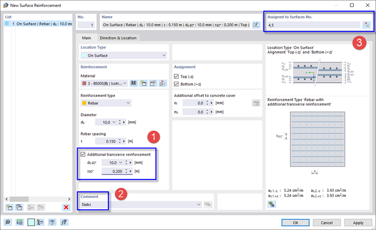
The reinforcement is defined by rebars 10 mm in diameter and 15 cm in spacing. It is assigned to the top and bottom sides of a surface. These rebars represent the primary (or principal) surface reinforcement. It runs parallel to the x-axis of the surface by default. Depending on the axes of the designed surfaces, the reinforcement is to be rotated when it is assigned to a surface (see below).
To add a secondary transverse reinforcement, select the Additional transverse reinforcement option (1). The diameter of the rebars is preset at 10 mm. Increase the spacing to 0.20 mm in the 's90°' box.
In the bottom-right area of the dialog box, the values of the primary reinforcement (5.24 cm2/m) and of the transverse reinforcement (3.93 cm2/m) are specified.
Enter Slabs in the 'Comment' area (2) to label this type of reinforcement.
To assign the reinforcement to the slabs graphically, use the
![]() button in the 'Assigned to Surfaces No.' area (3). The model view and the 'Surfaces Assignment' dialog box are presented.
button in the 'Assigned to Surfaces No.' area (3). The model view and the 'Surfaces Assignment' dialog box are presented.
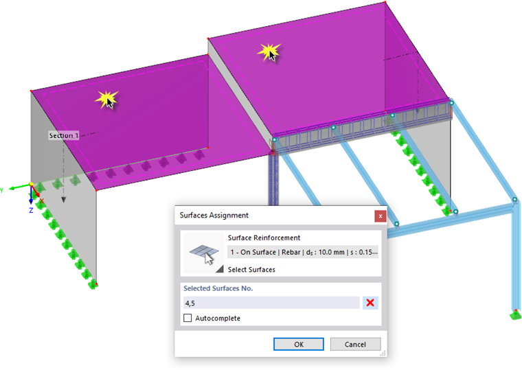
Select the two slabs by clicking surfaces nos. 4 and 5 one after another. If necessary, activate the 'Transparent Model' view by selecting the relevant option from the
![]() list button on the toolbar. Then click OK to return to the 'New Surface Reinforcement' dialog box.
list button on the toolbar. Then click OK to return to the 'New Surface Reinforcement' dialog box.
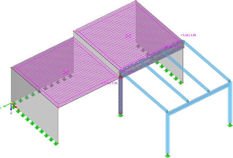
Close the dialog box by clicking OK. The rebars are displayed on the two slabs.
Adjusting the Design Properties
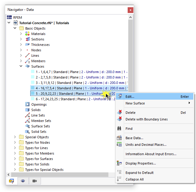
To check and adjust the design properties of the slabs, select surfaces nos. 4 and 5 in the 'Navigator - Data' one after another while holding down the Ctrl key. Then right-click one of the selected surfaces to open the shortcut menu. Select the Edit option.
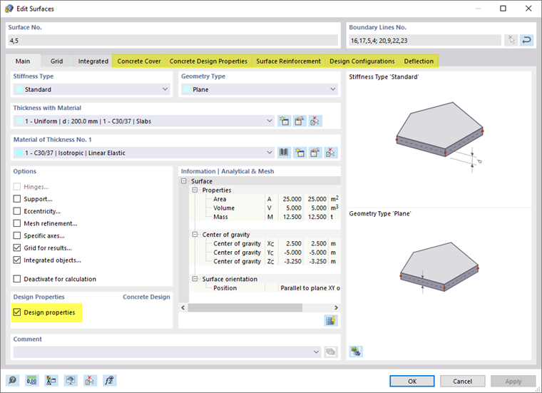
When you enabled the concrete design in the 'Base Data' (see the Activating 'Concrete Design' Add-on image), extra features were activated for the surfaces – the 'Design properties'. New tabs are thus available in the 'Edit Surfaces' dialog box to control the concrete design settings.
Concrete Cover
Select the Concrete Cover tab.
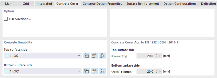
In the 'Concrete Durability' area, the 'XC1' category is preset for the top and bottom sides of the slabs. It controls the concrete cover according to the standard.
Concrete Design Properties
Select the Concrete Design Properties tab next.
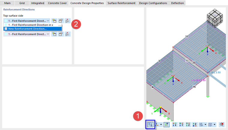
This tab controls the angle that defines the direction of the primary reinforcement within each surface. It is referred to the local axes of the surfaces. To check those axes, click the
![]() button in the bottom-right area (1) so that the model view is displayed in the dialog box.
button in the bottom-right area (1) so that the model view is displayed in the dialog box.
When you open one of the lists in the 'Reinforcement Directions' area, you will find the 'First Reinforcement Direction in x' option available for selection. As the primary spanning direction is parallel to the y-axes of the two slabs, however, a new direction must be created. Select the New Reinforcement Direction option in the list (2) or click the
![]() button to the right. A new dialog box opens.
button to the right. A new dialog box opens.
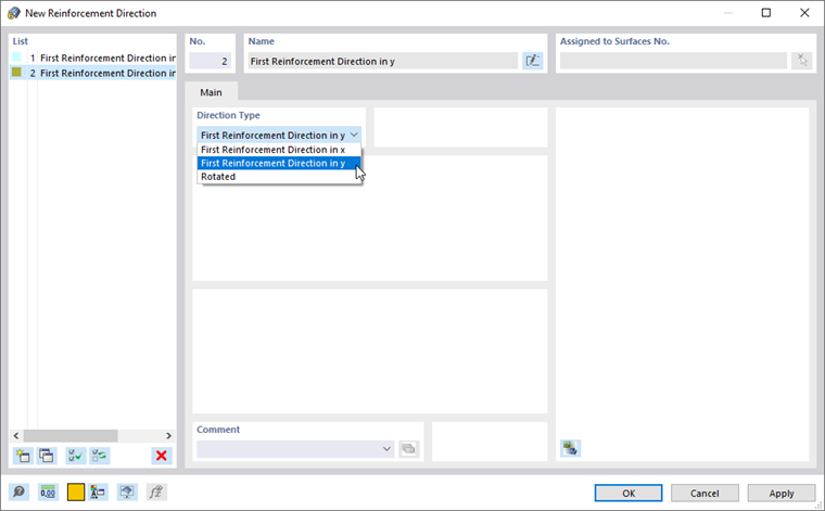
In the 'Direction Type' area, select the First Reinforcement Direction in y option from the list. Click OK to close the dialog box and return to the 'Concrete Design Properties' tab.
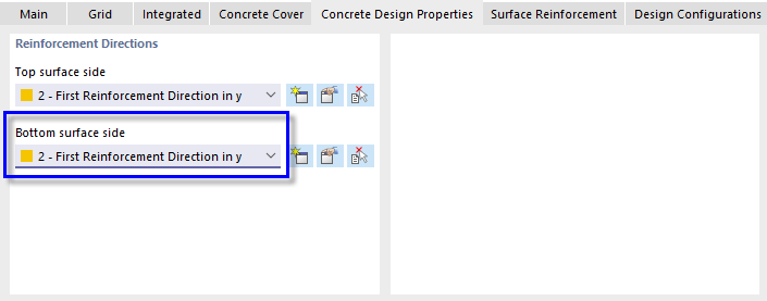
Select the 2 - First Reinforcement Direction in y option for the 'Bottom surface side', too.
Surface Reinforcement
Select the Surface Reinforcement tab next.
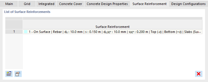
The '1 - On Surface | Rebar | ds : 10 mm | s : 0.150 m' reinforcement is preset for the slabs.
Design Configurations
Finally, select the Design Configurations tab.
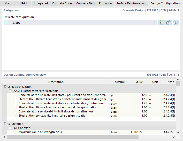
The 'Slabs' configuration type is preset. It accounts for optimization of the design internal forces and for the minimum reinforcement of slabs (see the Ultimate Configuration for Slabs image).
The 'Deflection' tab is not relevant because the SLS design was deactivated. Therefore, click OK to apply the modified rebar layout and close the dialog box.
