


For a better view of the results, switch off the rebars and stirrups in the Navigator – Display again by clearing the Reinforcement check box (see the image Switching off Reinforcements ).
In the Navigator – Results, the two main categories of the concrete design ("Design Checks" and "Reinforcement") now include the results of both members and surfaces. Clear the two On Surfaces check boxes so that only the member results will be shown on the model.
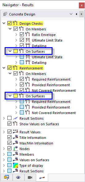
The "Design Checks" items correspond to those of the "Design Ratios on Members" tables, while the "Reinforcement" items correspond to those of the "Reinforcement on Members" tables (see the chapter Result Tables).
Design Checks
The design checks are split into "Ratio Envelope", "Ultimate Limit State", and "Detailing".
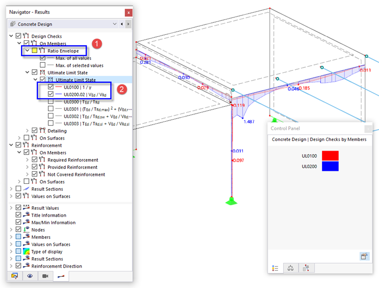
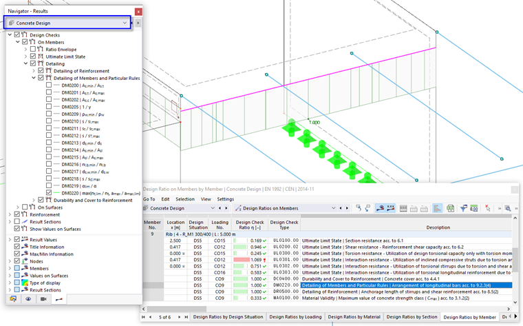
Clear the Ratio Envelope check box for a specific inspection of the single types of results (1). Select the 1/γ and VEd/VRd items of the ULS category so that the ratios of the section resistance and of the shear resistance are displayed (2).
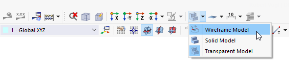
For a better view, select the Wireframe Model option, which you can access by clicking the
![]() button in the toolbar.
button in the toolbar.
The shear design results of the rib member ("UL0200" diagram) show higher ratios at the supporting column. They are not relevant to the design, but can be reduced by increasing the shear reinforcement (see below).
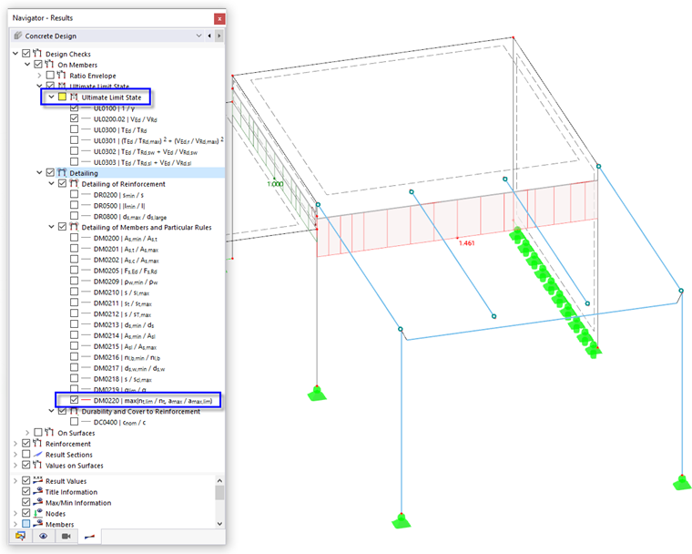
To check the problems concerning the detailing (see the image Table "Design Ratios by Member" ), clear the Ultimate Limit State check box, then activate the max(nt,lim / nt, amax / amax, lim) item in the "Detailing of Members and Particular Rules" category. The "DM0220" diagram reflects the high design ratios concerning the longitudinal bars of the rib.
To modify the rib reinforcement, double-click Member 9. Then select the Longitudinal Reinforcement tab in the "Edit Member" dialog box that opens.
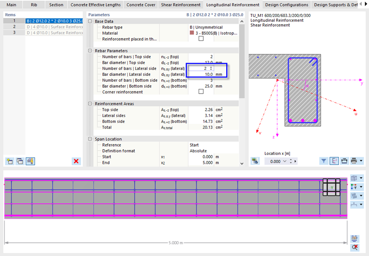
To define two rebars for the lateral sides of the rib beam, click the "ns,±y(lateral)" box and enter (or select) 2 rebars. Make sure that the bar diameter is set as 10 mm in the box below. Two rebars are created between the top and bottom reinforcements.
Select the Shear Reinforcement tab next.
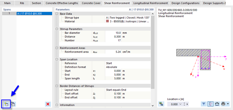
Click the
![]() button in the "Spans" area to create a new shear reinforcement span.
button in the "Spans" area to create a new shear reinforcement span.
There are two spans of equal length now. Select Span 1 (1).
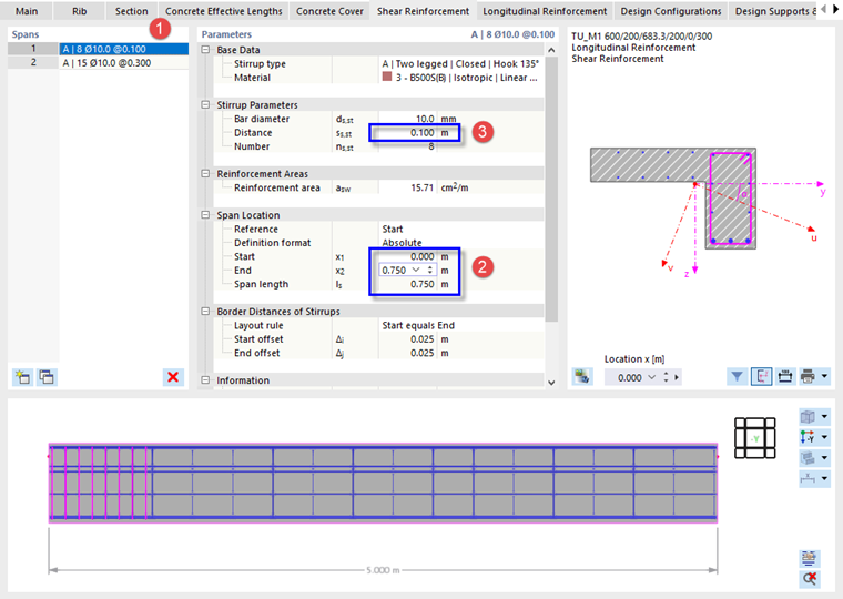
In the "Span Location" category, click the End box and enter 0.75 m to adjust the length of the shear reinforcement span (2). Then reduce the "Distance" of the stirrups by entering 0.10 m in the "Stirrup Parameters" category (3).
Close the dialog box by clicking OK and click Yes in the next dialog box again.
Finally, click the
![]() button in the toolbar to calculate all results.
button in the toolbar to calculate all results.
To display the design results again, set the Concrete Design option in the "Navigator – Results".
The design checks of the rib are almost all fulfilled now. The UL0301.00 check is slightly exceeded near the column, which is due to the torsional design. To solve this, you can
- Create a line mesh refinement of 0.1 m, for example, and apply it to line 20 (the line of the rib member), or
- Deactivate the design of the torsional moments for the rib design by means of a new Design Configuration where you disable the MT,Ed option.
Reinforcement
Deactivate the design ratios by clearing the Design Checks check box in the navigator. For a better view, collapse the "Design Checks" category (1).
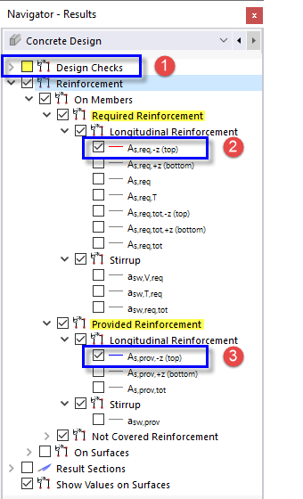
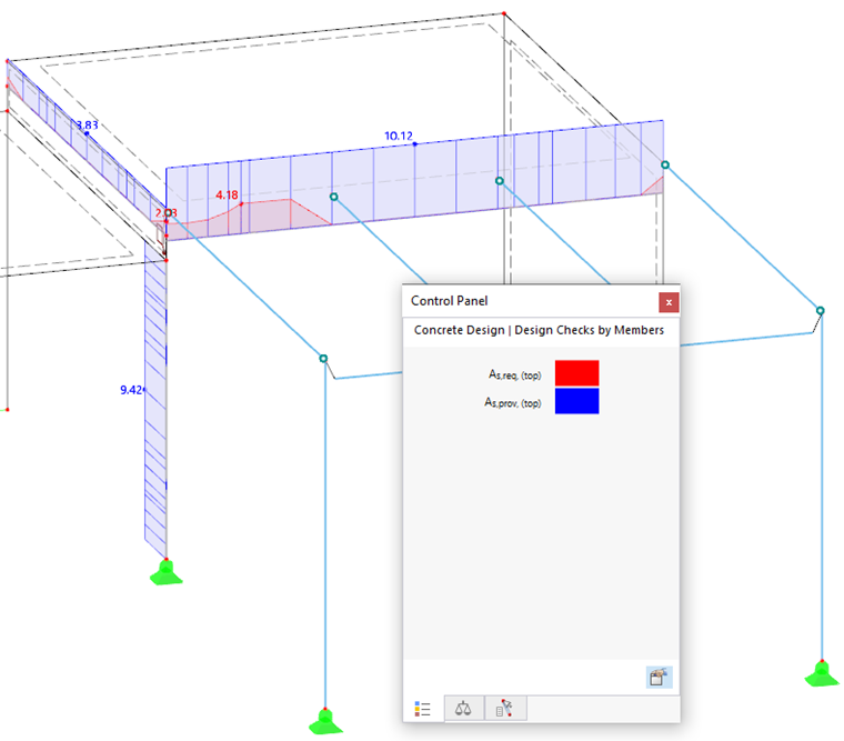
Select the As,req,-z(top) item of the "Longitudinal Reinforcement" subcategory, which you can find in the "Required Reinforcement" category of the member results (2). To compare the required top reinforcement to the provided top reinforcement, select the As,prov,-z(top) item of the "Provided Reinforcement" category below, too (3).
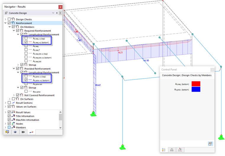
Clear the two check boxes again. To display the bottom reinforcements, select the As,req,+z(bottom) and As,prov,+z(bottom) items. You can examine the two diagrams of the required and provided reinforcements again.
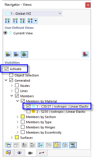
When you activate the "Visibilities" for the members of the 1 - C30/37 material only in "Navigator – Views", all other objects will be dimmed. If necessary, clear the Members by Section and Surfaces check boxes.
To print the Required and Provided Bottom Reinforcements image, click the
![]() button next to the
button next to the
![]() button on the toolbar. Select the Print Graphics to Printout Report option (see the image
Options "Print Graphics"
).
button on the toolbar. Select the Print Graphics to Printout Report option (see the image
Options "Print Graphics"
).
The preview of the image is presented with the familiar options to adjust the layout.
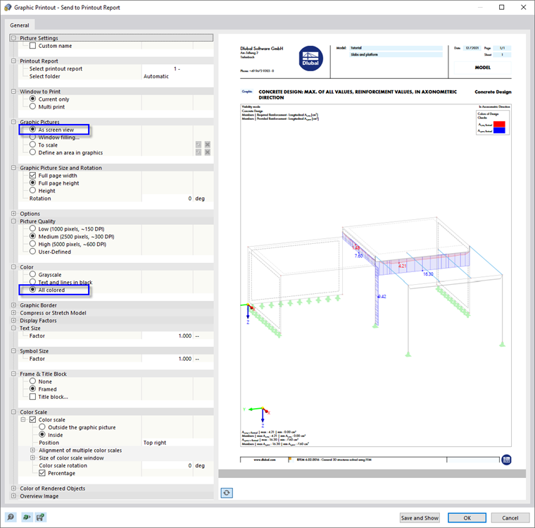
In the "Graphic Pictures" category, set the As screen view option. Then select All colored in the "Color" category. Click OK to send the image to the printout report without opening it.
Finally, clear the Activate check box of the "Visibilities" (see the image Activating Visibility for Concrete Members) so that all objects are displayed again.