You can also examine the design results graphically on the model, which gives you a better insight into the conditions of each surface.
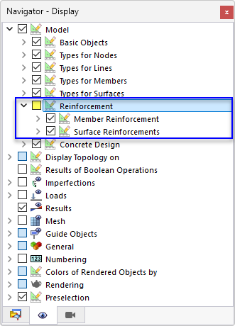
For an improved view of the results, switch off the display of the bar and mesh reinforcements: Select the Navigator – Display by clicking the
![]() tab. In the "Model" tree item, clear the Reinforcement check box.
tab. In the "Model" tree item, clear the Reinforcement check box.
Set the Navigator – Results by clicking the
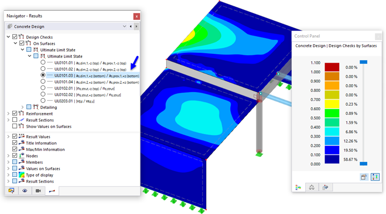
![]() tab. In the upper section, the concrete design results are arranged in two main categories: "Design Checks" and "Reinforcement".
tab. In the upper section, the concrete design results are arranged in two main categories: "Design Checks" and "Reinforcement".
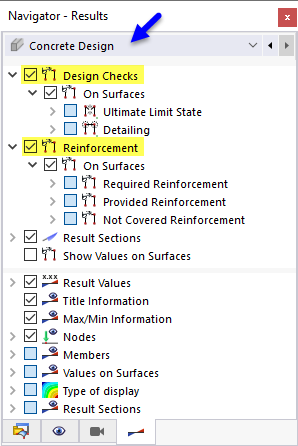
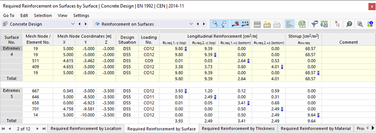
The "Design Checks" items correspond to those of the "Design Ratios on Surfaces" tables, the "Reinforcement" items to the ones of the "Reinforcement on Surfaces" tables (see the chapter Result Tables).
Additionally, the values along the "Result Sections" (defined in Part 1) are displayed by default. You can clear that check box for an exclusive view of the surface results.
Design Checks
The design checks are split into "Ultimate Limit State" and "Detailing" results. Select the as,dim1,-z(top) / as,prov1,-z(top) item of the ULS category. The ratios of the required reinforcement areas and the provided reinforcement areas are displayed. They refer to the primary reinforcement which is located on the top side of each surface.
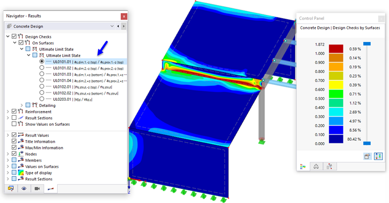
The ratios are met in the slabs and walls, except for the connecting surface where the ratios are greater than 1 in some areas. This Surface 6 virtually represents a deep beam. To verify it as a surface, it would be necessary to increase its primary reinforcement. An adequate solution can be achieved, however, by means of a member design using the "Result Beam" (see the chapter Result Beam).
To exclude the design results of the connecting surface from the display of ratios, click the
![]() tab of the control panel (1).
tab of the control panel (1).
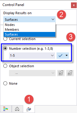
In the "Display Results on" area, select the Surfaces option from the list (2). Then, set the Number selection and enter 1-5 in the text box below (3). When you click the
![]() button next to it, the results of Surface 6 are no longer displayed.
button next to it, the results of Surface 6 are no longer displayed.
Select the as,dim1,+z(bottom) / as,prov1,+z(bottom) item of the ULS category to display the ratios of the primary reinforcement located on the bottom sides. Return to the colors overview of the panel by clicking the
![]() tab.
tab.
Select the vEd / vRd,c item to check the ratios of the shear resistance and shear capacity without reinforcement.
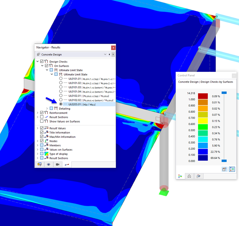
You can see some red peaks in the corners of the slabs. Zoom into the area near the column to have a closer look at the design checks greater than 1. The dark red ratios are located in and near the diameter of the column section. They can be qualified as singularities which are explained in the chapter Non-Designable Results.
Reinforcement
The graphical output of the reinforcement is split into the "Required Reinforcement" and "Provided Reinforcement" categories. Select the as,req,1,+z(bottom) item of the "Longitudinal Reinforcement" category.
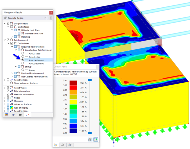
The bottom sides of the walls represent their outer sides.
Select the as,req,2,+z(bottom) item to display the secondary reinforcement (1). For the slabs, its direction runs parallel to the longer edge of the connecting surface between them.
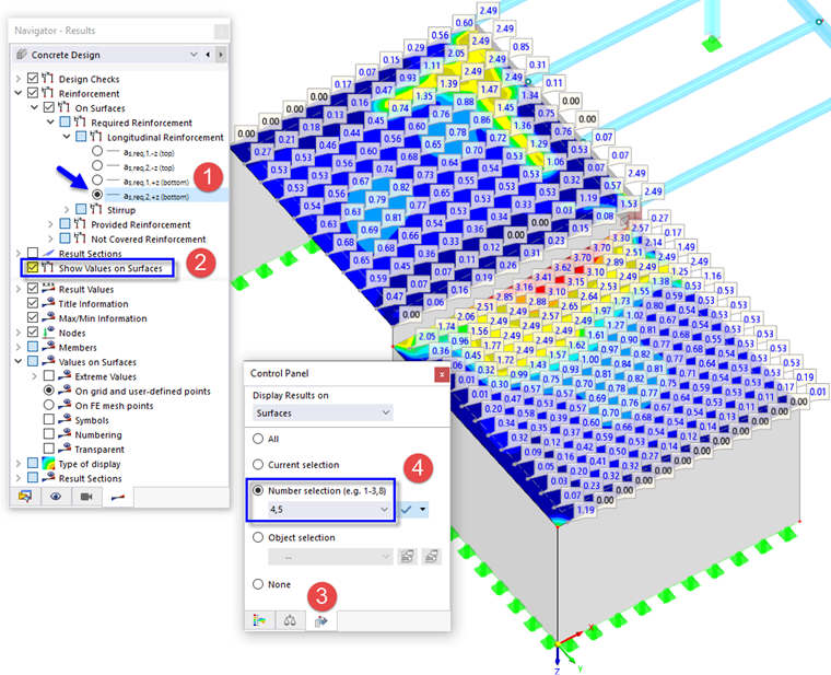
To display the values in the grid points, activate the Values on Surfaces check box (2). You will notice the different grid layout of the two slabs (a smaller grid was defined for the lower slab; see Part 1). Click the
![]() tab of the panel again (3). To display the results of the slabs exclusively, enter the numbers of Surfaces 4,5 and press ENTER (4).
tab of the panel again (3). To display the results of the slabs exclusively, enter the numbers of Surfaces 4,5 and press ENTER (4).
The results of the tables are synchronized with the work window: When you set the Required Reinforcement on Surfaces by Surface table, only the extremes of the two slabs are listed.