


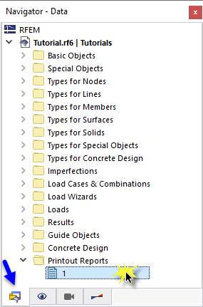
The concrete design data can be added to the printout report that was created in Part 1. To open this document, double-click the 1 item in the 'Printout Reports' category of the 'Navigator - Data'.
In the printout report, open the 'Printout Report Manager' by clicking the
![]() button on the toolbar (second from the right). Alternatively, select Edit Printout Report on the Edit menu.
button on the toolbar (second from the right). Alternatively, select Edit Printout Report on the Edit menu.
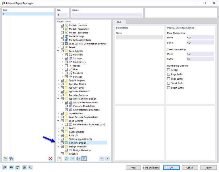
Activate the Concrete Design report item folder to include the design data. Then click Save and Show.
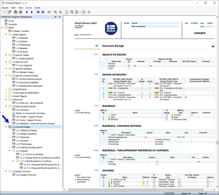
Chapter 11 of the printout report contains the default data of the concrete design.
Adjusting the Contents
To add or remove a chapter, you can use the Printout Report Manager as described in Part 1. It is also possible to delete an item directly: Right-click 11.7.1 Errors & Warnings, for example, to open the shortcut menu of this chapter. There select Remove from Printout Report.
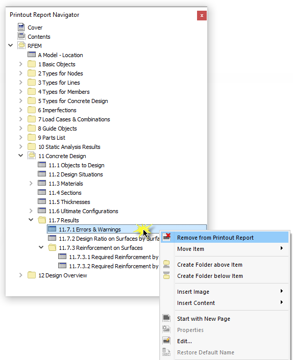
The printout report is updated without the warnings.
Printing Graphics
To add an image to the printout report, minimize the preview window by clicking the
![]() button on the 'Printout Report' title bar. The RFEM workspace is displayed again in full view.
button on the 'Printout Report' title bar. The RFEM workspace is displayed again in full view.
Set the Navigator - Results again (1) so that you can select the required longitudinal reinforcement as,req,1+z(bottom) for display (2). Make sure that the 'Show Values on Surfaces' option is activated, too (3).
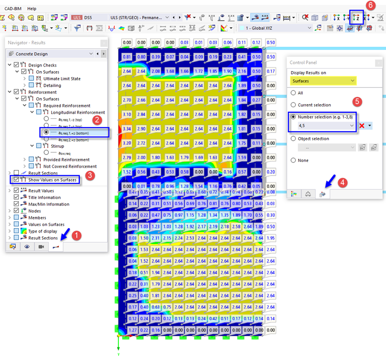
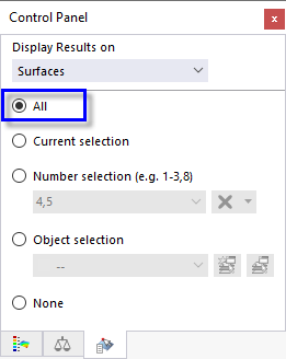
To display only the results of the slabs, click the third tab of the panel (4) and check whether the surfaces nos. 4,5 are selected (5). Finally, click the
![]() button on the toolbar to set the top view (6).
button on the toolbar to set the top view (6).
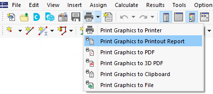
To print this image, click the
![]() button next to the
button next to the
![]() button on the toolbar. A list of printing options is opened. Click Print Graphics to Printout Report.
button on the toolbar. A list of printing options is opened. Click Print Graphics to Printout Report.
The preview of the image is presented with some options to adjust the layout.
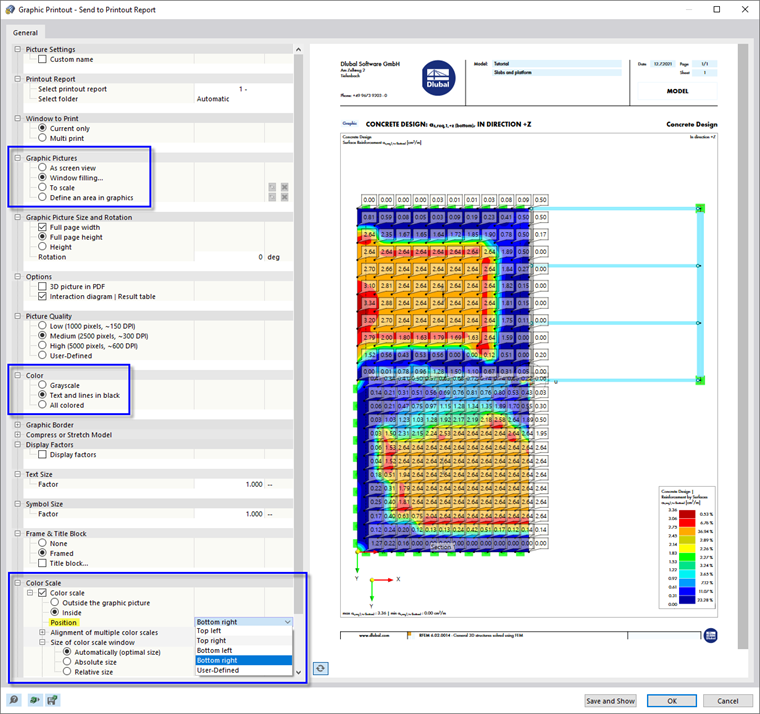
In the 'Graphic Pictures' area, select the Window filling arrangement. Set the Text and lines in black layout in the 'Color' area so that the values are easy to read. To move the panel to a different position, select the Bottom right option from the list in the 'Color Scale' area. Then click Save and Show.
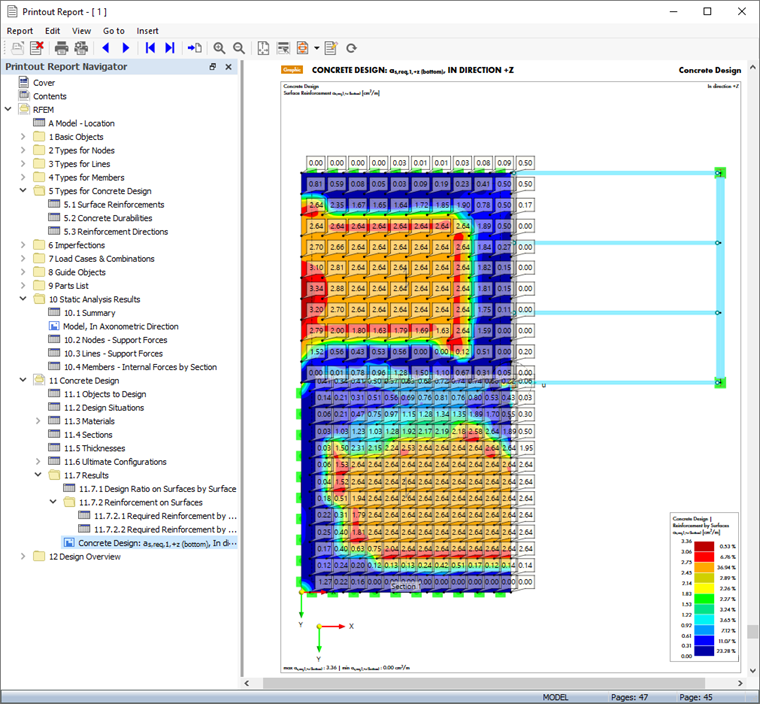
The printout report is created again, with the image on the last page of the 'Concrete Design' chapter.
Close the printout report by clicking the
![]() button.
button.
Before you continue with the design of the concrete members, restore the display of All surfaces in the panel.
Finally, save the concrete design data of the surfaces by clicking the
![]() button on the toolbar.
button on the toolbar.