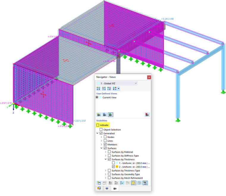
Next, the design parameters of the three walls and of the connecting surface between the slabs are to be defined. To select these surfaces, use the visibilities: Open the 'Navigator - Views' by clicking the
![]() tab.
tab.
Open the Surfaces by Thickness item and activate the wall type thickness, no. 2, by selecting its check box (1) while the slab type thickness is deactivated. Make sure that the 'Activate' check box at the top and the 'Surfaces' category are selected, as well (2).
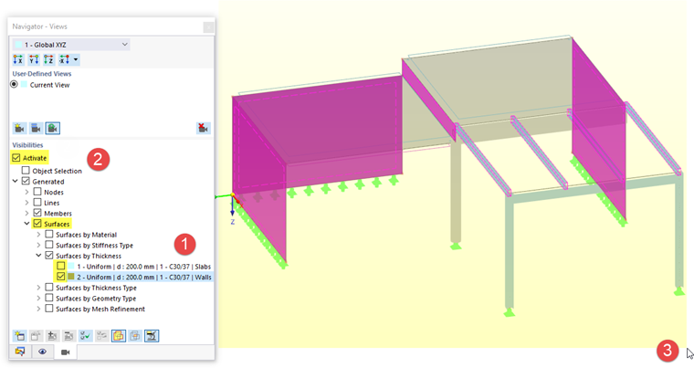
Draw a window over the entire model (3). Then double-click one of the selected surfaces to open the 'Edit Surfaces' dialog box and allocate the design properties.
Concrete Cover
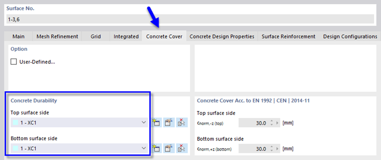
Select the Concrete Cover tab. In the 'Concrete Durability' area, the 'XC1' category is preset for the top and bottom sides of the walls.
Concrete Design Properties
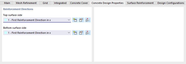
On the Concrete Design Properties tab, the 'First Reinforcement Direction in x' option is preset for the top and bottom sides. The direction of the reinforcement is of minor relevance, as a Q-mesh reinforcement (square welded wire mesh) with uniformly placed wires is to be applied.
Surface Reinforcement
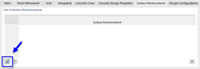
On the Surface Reinforcement tab, click the
![]() button to define a new type of reinforcement. A new dialog box opens.
button to define a new type of reinforcement. A new dialog box opens.
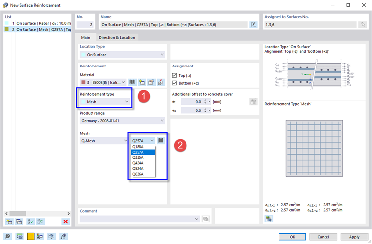
In the 'Reinforcement' area, the 'BS500(B)' material is preset. Select the Mesh reinforcement type from the list (1). By doing so, the 'Q-Mesh' type of welded wire fabric according to the German product range is set. Select the Q257A size (2).
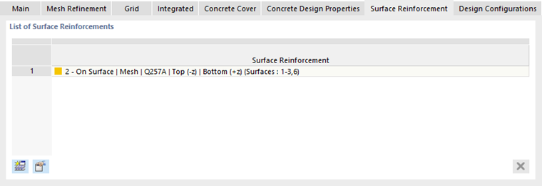
Make sure that the reinforcement is assigned to the 'Top' and 'Bottom' sides of the surfaces. Then click OK to close the 'New Surface Reinforcement' dialog box and apply it on the 'Surface Reinforcement' tab.
Design Configurations
Finally, select the Design Configurations tab.
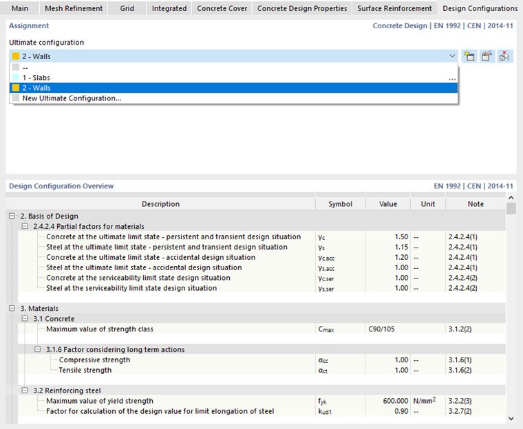
Select the Walls configuration type from the list.
Having now defined all parameters of the reinforcement, click OK to apply the wire mesh to the walls. When you clear the Activate check box of the 'Visibilities', all objects of the model are displayed again.