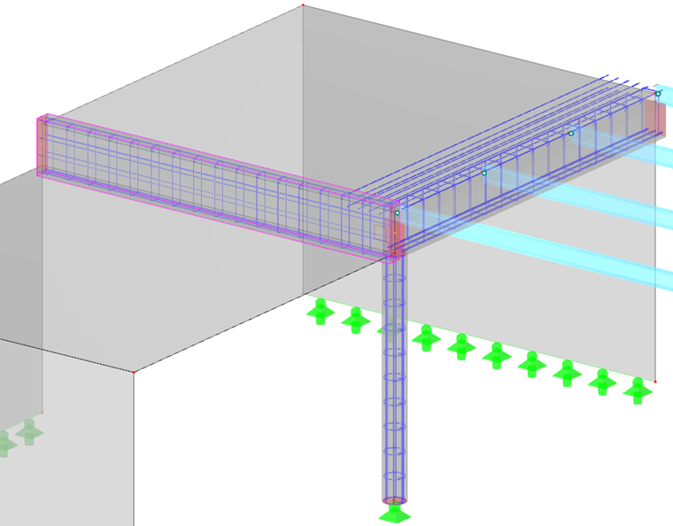
The connecting surface virtually represents a deep beam. It can also be designed by means of a specific member element – the so-called result beam – to integrate the results of the surface and perform the concrete design. Its outstanding advantage is that the longitudinal reinforcement can be arranged on the top and bottom sides of the beam instead of the sides of the surface.
The centre axis of a result beam must coincide with the centroid of the object in question so that the internal forces are integrated with the correct lever arm. Therefore, it is necessary to create a new line along the centre line of the connecting surface. This can be done by defining the result beam directly.
New Member
Click the
![]() button on the toolbar to create a new member. In the 'New Member' dialog box, select the Result Beam option from the list in the 'Member Type' area.
button on the toolbar to create a new member. In the 'New Member' dialog box, select the Result Beam option from the list in the 'Member Type' area.
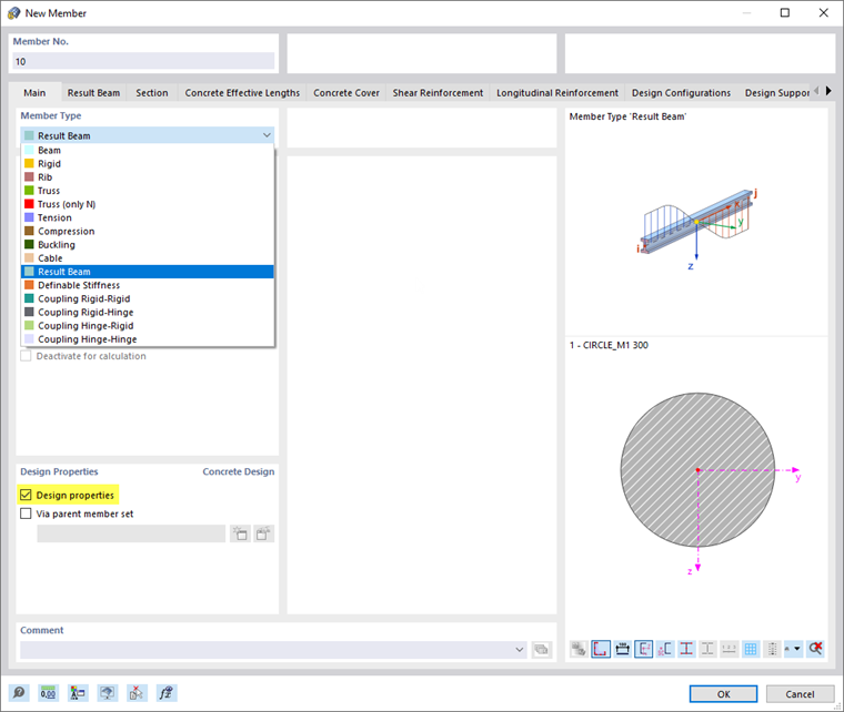
Result Beam
Then go to the Result Beam tab. In the 'Integrate Stresses and Forces' area, select the Integrate stresses and forces from listed objects option to avoid defining any geometry (1).
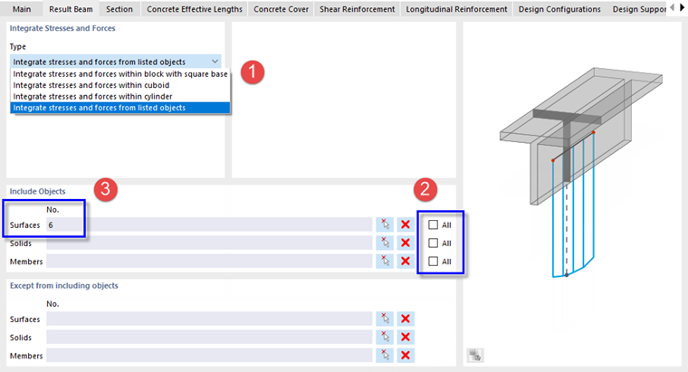
Next disable the three All check boxes in the 'Include Objects' area (2). In the 'Surfaces' box, enter the number of the connecting surface no. 6 so that only the results of this surface are integrated (3).
Section
To define the section of the result beam, select the Section tab.
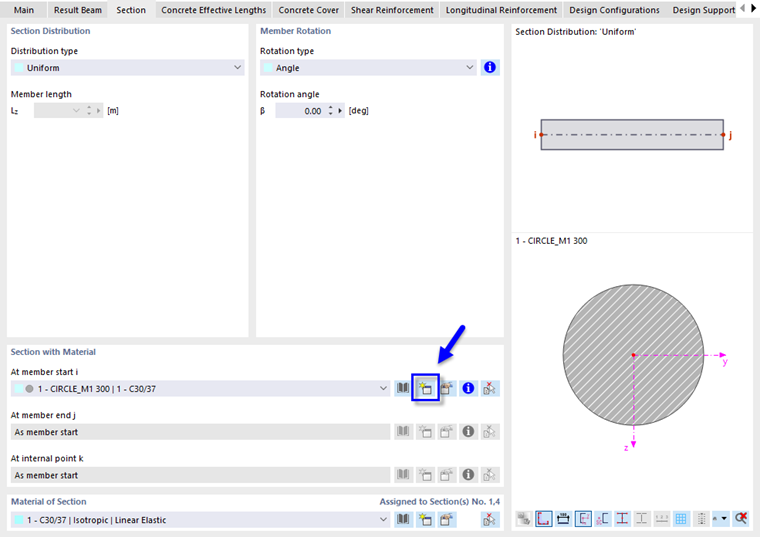
To define a new section representing the shape of the connecting surface, click the
![]() button in the 'Section with Material' area. The 'New Section' dialog box opens.
button in the 'Section with Material' area. The 'New Section' dialog box opens.
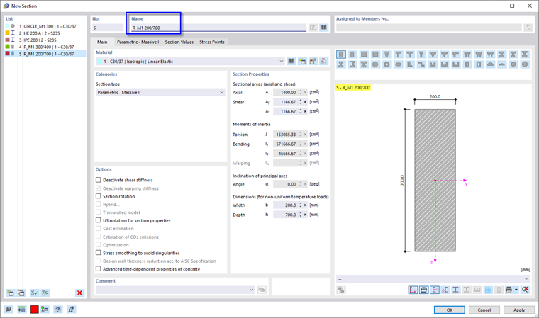
A parametric 'R_M1' section is preset. In the 'Name' area, change the parameters to 200/700 by modifying the values. Then click OK to apply the section with the height of 70 cm (the total height between the bottom side of the lower slab and the top side of the upper slab) and the width of 20 cm (the thickness of the surface). The new section no. '5' is entered in the 'New Member' dialog box.
Concrete Cover
Select the Concrete Cover tab and make sure that the 'XC1' category is set.
Reinforcement
Select the Longitudinal Reinforcement tab next.
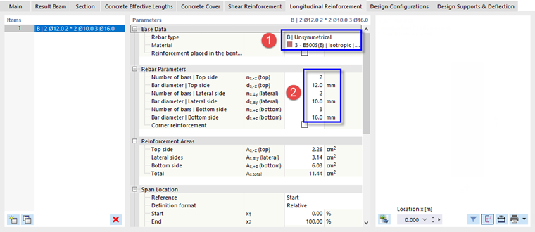
Select the B | Unsymmetrical option from the list of layout types in the 'Base Data' category (1). Make sure that the 3 - B500S(B) material is set in the line below.
In the 'Rebar Parameters' category, define the different layout of the rebars for the top, bottom and lateral sides of the beam (2):
- In the 'ns,-z(top)' box, enter (or select) 2 rebars. In the box below, adjust the bar diameter to 12 mm.
- In the 'ns,+/-y(lateral)' box, enter 2 rebars. In the box below, make sure that the bar diameter is preset to '10' mm. Two rebars will be created between the top and bottom reinforcement.
- In the 'ds,+z(bottom)' box, define the diameter of the three rebars at the bottom as 16 mm.
There is no preview of the reinforcement shown because the line has not been defined yet.
Line
Click OK to define the line now. The 'New Member | Single | Simple' dialog box opens.
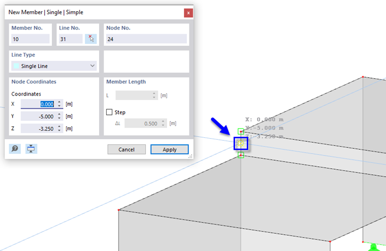
Zoom into the area at the rear side of the connecting surface. Then move the pointer along its vertical boundary line until the
![]() symbol appears at the pointer and the coordinates [X: 0 m / Y: -5 m / Z: -3.25 m] are displayed in the dialog box. Click this point.
symbol appears at the pointer and the coordinates [X: 0 m / Y: -5 m / Z: -3.25 m] are displayed in the dialog box. Click this point.
To define the end point to the line, zoom into the area near the column. You can manage it without terminating the 'New Member' function by using the scroll wheel (zooming in or out) or by holding the mouse wheel down (moving the view).
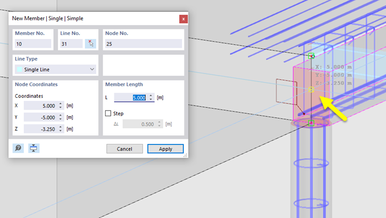
Move the pointer along the vertical boundary line of the connecting surface until the
![]() symbol appears at the pointer again. Make sure that the coordinates [X: 5 m / Y: -5 m / Z: -3.25 m] are displayed in the 'New Member' dialog box. Click that point to set the line and allocate the member properties.
symbol appears at the pointer again. Make sure that the coordinates [X: 5 m / Y: -5 m / Z: -3.25 m] are displayed in the 'New Member' dialog box. Click that point to set the line and allocate the member properties.
When the program asks you whether all results are to be deleted because of the modification, click Yes.
The reinforcement of the new member is displayed with stirrups at default spacings along the length of the beam. Click Cancel to quit setting lines.