The Errors & Warnings table shows some non-designable results and design ratios greater than 1. In almost all cases, the problems occur near nodes with "peaks" of stresses. They are due to singular effects that are not unusual according to the FEA approach. In those locations, the stresses are concentrated within a very small area. The singularities, however, do not occur to that extent in reality: For example, the forces of the lower slab are not transferred to the column at a single node, which the "pinhead-shaped" modelling suggests. Instead, the diameter of the column and the thickness of the slab provide a smoother flow of the forces.
Basically, evaluating the results of locations with singularities is not really advisable (yet, examining those results is advisable for critical locations of the real model, such as the critical perimeter for punching near the column). In the following articles at our Knowledge Base, you will find detailed information on singularities, for example where they occur, how to detect them and what actions you can take:
- Singularities in the Design of Reinforced Concrete Surfaces
- Preventing Singularities on Nodal and Line Supports of Plate Structures
In the tutorial model, singularities occur at the column head and at the ends of the ribs and supporting walls. They can be identified by very high values within a relatively small area. Below you can find some tips for handling singularity effects.
Modelling supports with springs
Any rigid support represents an "infinite" stiffness. If the vertical supports of the column and walls are modelled by appropriate springs instead, the peaks of stresses will be distinctly reduced. The spring constants can be based on the results of a soil expertise, for example.
Ignoring results within areas of peaks
According to the rules of Eurocode 2, the design is to be carried out for the locations at a certain distance from the edges of a support (see EN 1992-1-1, 5.3.2.2). The peak values near the column head are therefore not relevant to the practical design. It is acceptable to ignore the results within the column diameter plus a certain perimeter beyond, for example.
Applying 'Surface Results Adjustments' feature
To compensate for the singularities, you can apply a specific feature of the program: The 'Surface Results Adjustments' enable you to smoothen out the values within a user-defined area.
To open the tool, select the 'Navigator - Data'. Then right-click the Surface Results Adjustments item in the Special Objects category.
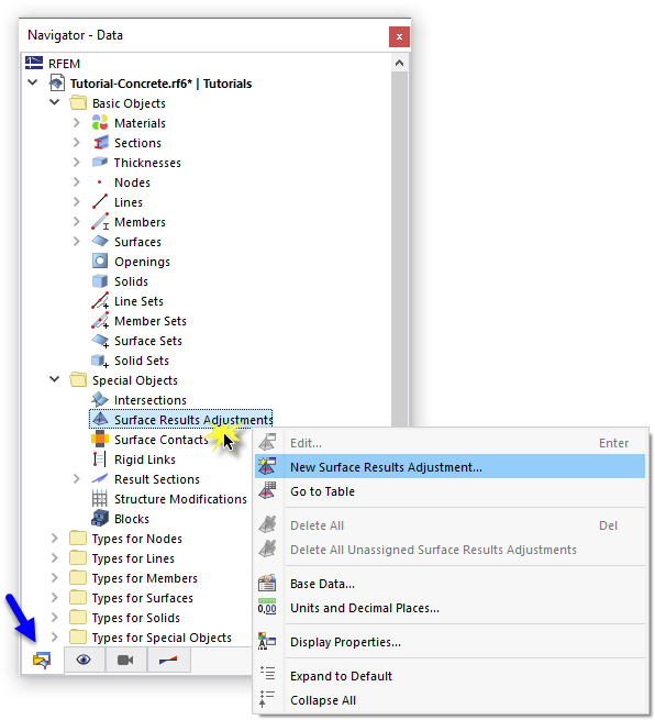
Select New Surface Results Adjustment in the shortcut menu to open the 'New Surface Results Adjustment' dialog box.
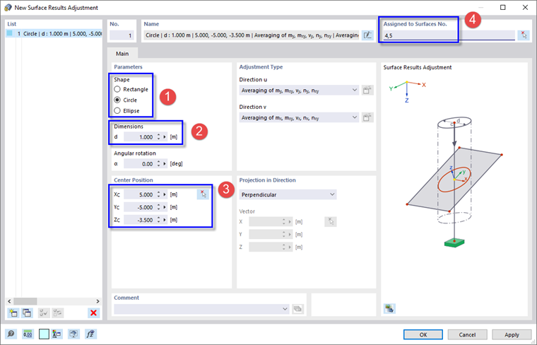
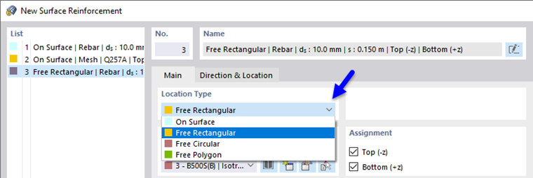
In the 'Parameters' area, select the Circle option to create a circular adjustment area (1). Enter the diameter of that area as 1.00 m (2), for example (which is twice the sum of the column diameter and surface thickness). In the 'Center Position' area, click the
![]() button to select the topmost node above the concrete column (no. 15) in the graphics so that its coordinates are applied (3). In the 'Assigned to Surfaces No.' area, enter the numbers of the slabs nos. 4,5 (4).
button to select the topmost node above the concrete column (no. 15) in the graphics so that its coordinates are applied (3). In the 'Assigned to Surfaces No.' area, enter the numbers of the slabs nos. 4,5 (4).
The settings define that the moments and membrane forces (see the 'Adjustment Type' area) of the two slabs will be averaged within the circular areas of the slabs around the column head. Click OK to apply the feature.
Click Yes to confirm the question whether the concrete design results are to be deleted. There will be no new calculation of the load cases and combinations, however: The results of the structural analysis are just converted.
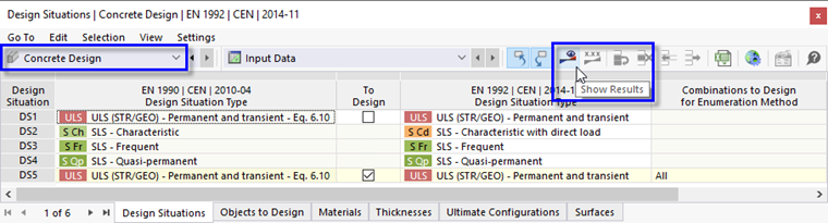
To calculate the reinforcement ratios with the new settings, select the Concrete Design table. Then click the
![]() button as before.
button as before.
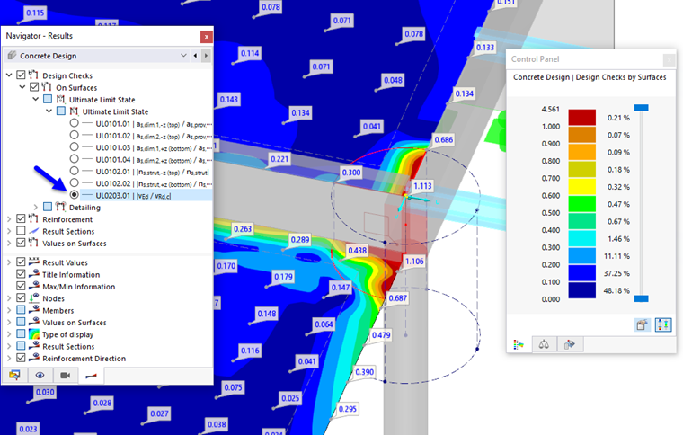
When you now check the shear design ratios around the column, for example, the results are now more acceptable than before (compare the Shear Design Ratios image).
The design ratios greater than 1 will have to be accounted for by specific provisions in the detailing of the reinforcement. Please note that punching design is not covered by this tutorial.