


If there are results shown on the model, switch them off by clicking the
![]() button on the toolbar.
button on the toolbar.
Set the axonometric view by clicking the
![]() button. You can see the reinforcement cages of the downstand beam and of the column. You can hide the cylinder symbol by deactivating the Result Objects in the 'Navigator - Display'.
button. You can see the reinforcement cages of the downstand beam and of the column. You can hide the cylinder symbol by deactivating the Result Objects in the 'Navigator - Display'.
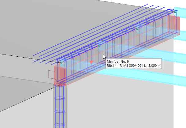
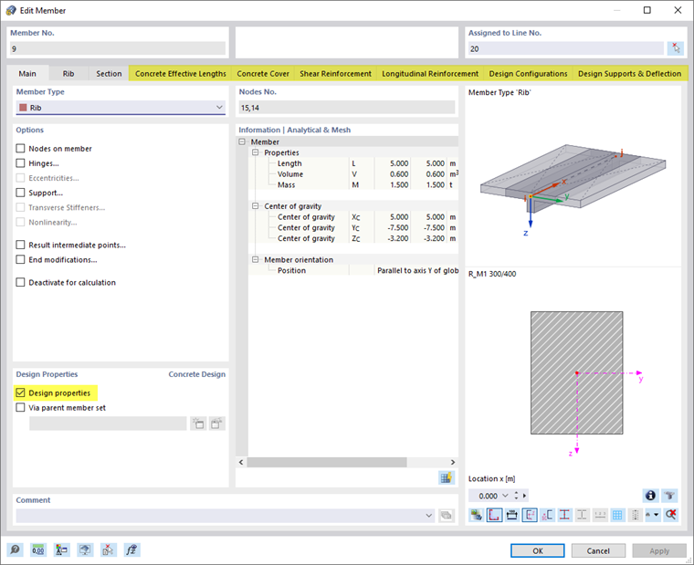
Double-click the downstand beam (member no. 9) to open the 'Edit Member' dialog box. On the first tab, the 'Design properties' are enabled so that additional tabs are available that control the settings.
Concrete Cover
Select the Concrete Cover tab.
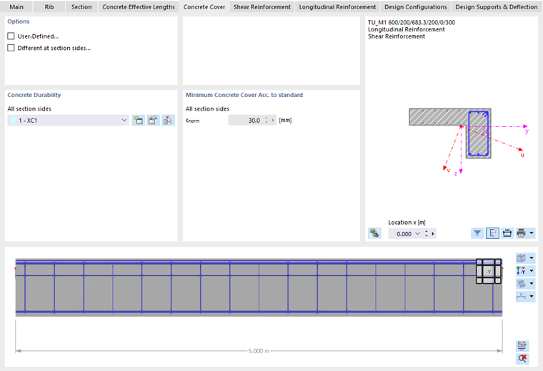
In the 'Concrete Durability' area, the XC1 category is preset for all sides of the beam. It controls the concrete cover according to the standard.
Shear Reinforcement
Select the Shear Reinforcement tab next.
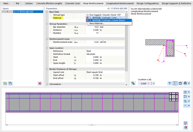
This tab manages the layout of the stirrups. To assign the 'Material', open the list of materials in the 'Base Data' category and select type 3 - B500S(B).
The diameter of the stirrups is preset by 10 mm and the longitudinal spacing by 30 cm. It would be possible to change either parameter here. The number of stirrups results from the spacing and the beam length.
Longitudinal Reinforcement
Finally, select the Longitudinal Reinforcement tab.
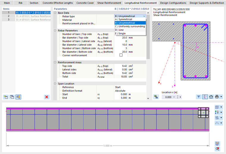
To define different rebars for the top and bottom sides of the beam, open the list of layout types in the 'Base Data' category. Select the B | Unsymmetrical option. Next set the 3 - B500S(B) material again in the line below (1).
In the 'Rebar Parameters' category, you can now define the different layout of the rebars for the top and bottom sides of the beam.
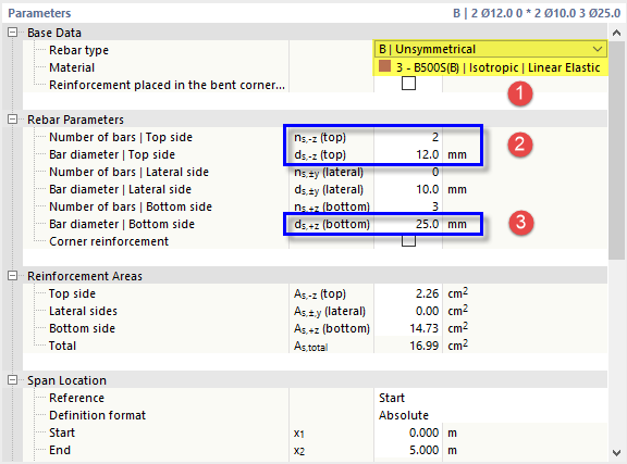
Click the 'ns,-z(top)' box and enter (or select) 2 rebars. In the box below, adjust the bar diameter to 12 mm (2). Then select the 'ds,+z(bottom)' box and define the diameter of the three rebars at the bottom as 25 mm (3).
You can then check the values listed in the 'Reinforcement Areas' category below.
With the
![]() button, you can switch the rebars of the flange on or off so that they are considered for the design or not. They represent the surface reinforcements that have been defined for the adjacent slab.
button, you can switch the rebars of the flange on or off so that they are considered for the design or not. They represent the surface reinforcements that have been defined for the adjacent slab.
Click OK to apply the reinforcement to the downstand beam and close the dialog box.