


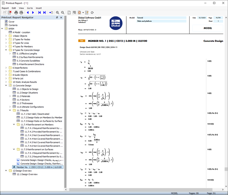
The concrete design data of the members is part of the printout report, too. Double-click the 1 item in the Printout Reports category of the 'Navigator - Data' again (see the Opening Printout Report image). Chapter 11 now also includes the design results of the concrete members.

Chapter 11.7.4.1 contains the required reinforcement of the concrete members.
The design details that you have printed in the table (see the Design Check Details of Column image) are placed at the end of Chapter 11. If you want, you can drag that item to another location, for example after Chapter 11.7.4.
Adjusting an Image
The printout report also includes the image of the bottom reinforcements. Select it in the navigator (1). To change the area of the view, right-click the image (2).
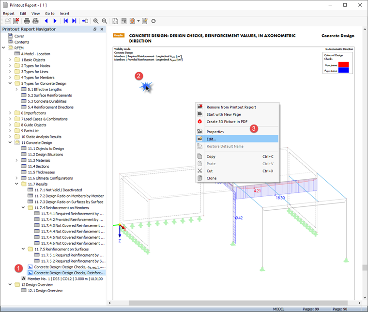
Select the Edit option on the shortcut menu (3). You return to the workspace of RFEM where you can resize the image by dragging the borders of the grey rectangle.
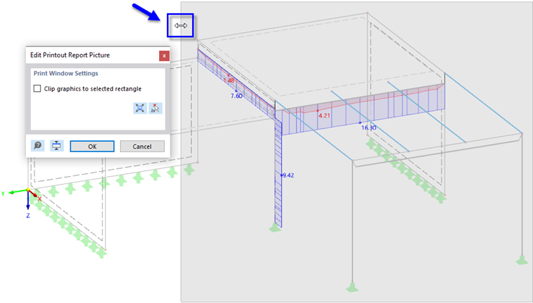
Click OK to apply the new clipping area and update the image in the printout report.
Close the printout report by clicking the
![]() button.
button.
You have now completed the concrete design part of the tutorial. Save the data by clicking the
![]() button on the toolbar.
button on the toolbar.