


Double-click the column (member no. 1) to open the 'Edit Member' dialog box. The settings are slightly different, as the stability of the column is to be verified additionally.
Concrete Cover
Select the Concrete Cover tab and make sure that the 'XC1' category is set.
Shear Reinforcement
Select the Shear Reinforcement tab next.
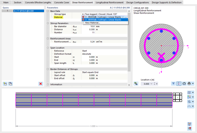
In the 'Base Data' category, select type 3 - B500S(B) from the list of materials again.
The default settings of the stirrups (Ø 10 mm, s = 0.30 m) are suitable for the design.
Longitudinal Reinforcement
Select the Longitudinal Reinforcement tab.
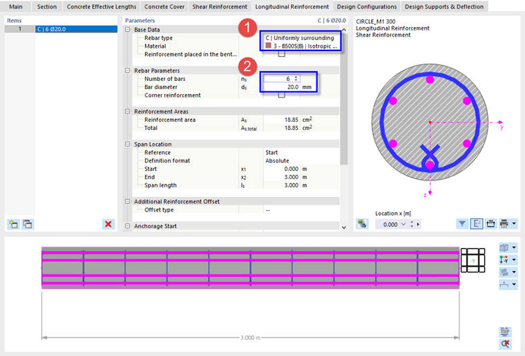
Open the list of layout types in the 'Base Data' category. Select the C | Uniformly surrounding option (1). Next, set the 3 - B500S(B) material again in the line below.
In the 'Rebar Parameters' category, enter (or select) 6 rebars in the 'ns' box (2). The bar diameter of 20 mm is suitable for the design.
Concrete Effective Lengths
Finally, select the Concrete Effective Lengths tab to define the buckling parameters of the column. They are required for the design according to the method based on nominal curvature as specified in EN 1992-1-1, 5.8.8.
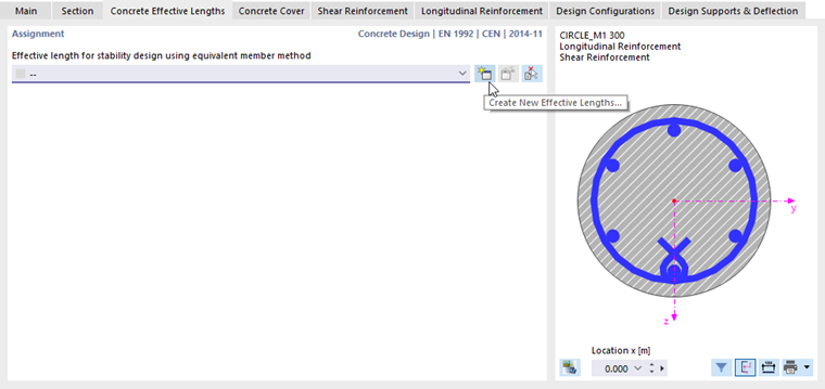
Flexural buckling is only analyzed when the effective lengths of the member are defined. Click the
![]() button in the 'Assignment' area to create a new type of effective length. Another dialog box opens.
button in the 'Assignment' area to create a new type of effective length. Another dialog box opens.
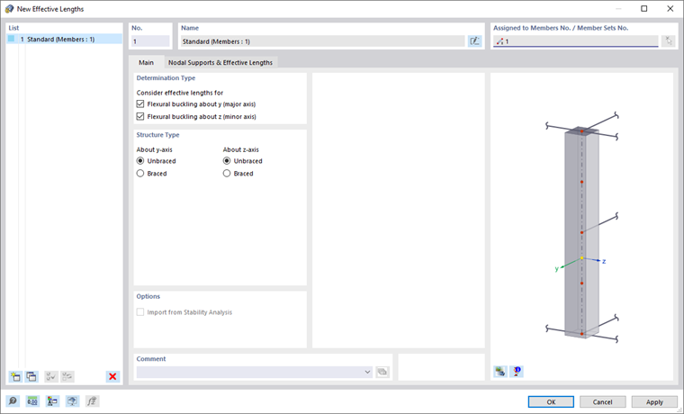
By default, the buckling design is carried out for both principal axes of the unbraced member.
Select the Nodal Supports & Effective Lengths tab.
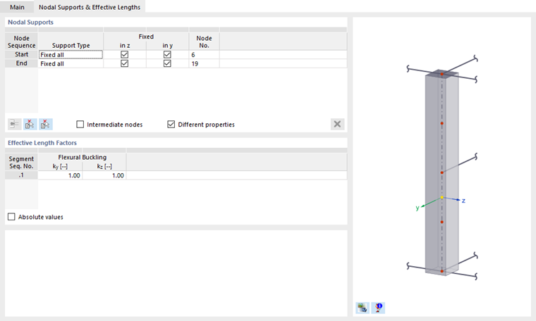
The column has pinned supports at both ends. It would be possible to reduce the buckling lengths because the column head is restrained by the slabs to a certain degree. For a conservative approach, however, unbraced settings with effective length factors k = 1.0 of a pin-ended column are to be applied.
Click OK to close the dialog box and return to the 'Concrete Effective Lengths' tab.
Having defined the design settings of the column now, click OK to close the 'Edit Member' dialog box.