


There are new categories of the 'Concrete Design' results in the toolbar list that control the member results.
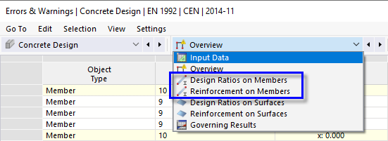
Design Ratios on Members
Select the Design Ratios on Members category (1). The design ratios of each member are listed by different criteria in five tables. Set the Design Ratios by Member table (2).
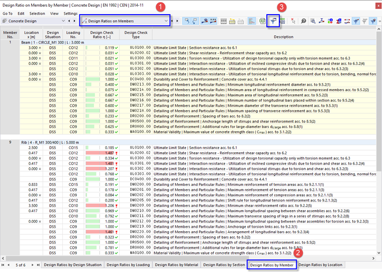
The values listed in the 'Design Check Ratio' column represent the quotients of the ULS design checks ('UL') and the checks of detailing ('DM' and 'DR'). For example, 'UL0200.02' represents the check of the shear resistance according to EN 1992-1-1, 6.2.
The design of the column is verified, but the ratios especially of the rib require attention. Some locations are directly at or near the supports of the column or wall so that they are not relevant to the shear design. Some warnings, however, refer to unmet design checks that are to be examined graphically later (see Chapter Graphical Results).
To reduce the contents of the table, click the
![]() button on the table toolbar (3). The 'Result Table Manager' is opened.
button on the table toolbar (3). The 'Result Table Manager' is opened.
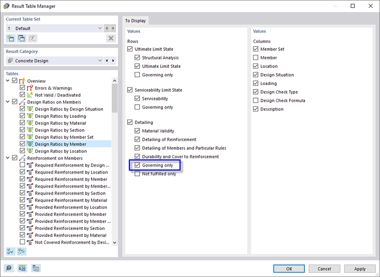
Select the Governing only check box of the 'Detailing' rows. When you click OK, the table is reduced to the essential results.
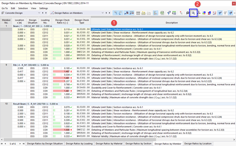
To check the ULS design details of the column, for example, select the first line of its results (1). 'UL0100.00' represents the check of the section resistance according to EN 1992-1-1, 6.1 with consideration of the nominal 2nd order moment. Then click the
![]() button on the table toolbar (2).
button on the table toolbar (2).
The 'Design Check Details' window opens.
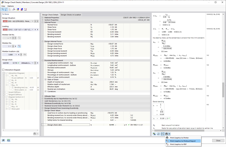
This window presents all parameters of the design and the relevant equations. By clicking the
![]() button in the bottom-right area, you can switch between values or symbols displayed in the formulas of the design.
button in the bottom-right area, you can switch between values or symbols displayed in the formulas of the design.
To print the details, click the
![]() button next to the
button next to the
![]() button. Select the Print Graphics to Printout Report option. The equations of this design check are exported to the report without opening it.
button. Select the Print Graphics to Printout Report option. The equations of this design check are exported to the report without opening it.
Return to the tables by clicking Close.
Reinforcement on Members
On the table toolbar, select the Reinforcement on Members category (1) as seen in the Categories for Member Results image. The reinforcement of each member is listed in several tables by different criteria again. Set the Required Reinforcement by Member table (2).
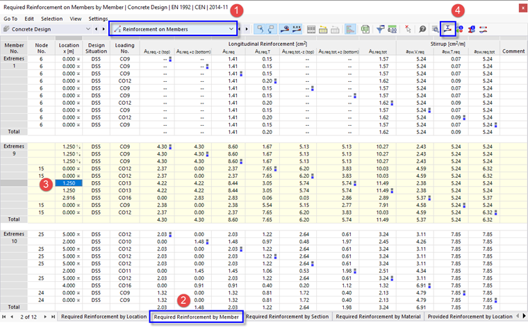
In this table, the extreme values of the required reinforcement are listed for every member. The maximum areas of every reinforcement category are labelled by
![]() symbols. You can also examine which load combination requires the maximum reinforcement each.
symbols. You can also examine which load combination requires the maximum reinforcement each.
As before, you can check the details of the design in the 'Design Check Details' dialog box (see the Design Check Details image): Select a line and then click the
![]() button on the table toolbar.
button on the table toolbar.
To check the stresses of the rebars in a diagram, select the line of the required bottom reinforcement area of the rib member no. 9, for example (3). Then click the
![]() button on the table toolbar (4).
button on the table toolbar (4).
The 'Result Diagrams in Section' window opens.
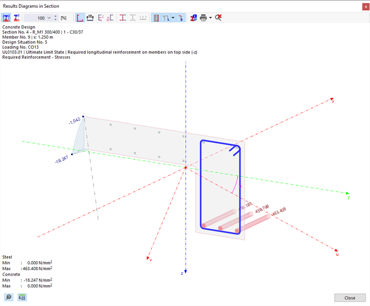
The diagram shows the stresses of the rebars and the concrete stresses. The toolbar buttons enable you to control the graphics and print the diagram.
Return to the tables by clicking Close.