


The 'Errors & Warnings' table is displayed by default. It gives an overview of the problems that have occurred during the design.
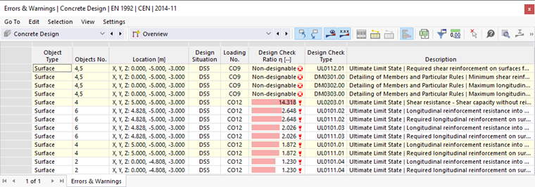
This table presents several non-designable or failed checks. Some of those results are located closely to or directly at a support of the surface so that they can be qualified as singularities. You can find more details on how to handle singularities in Chapter Non-Designable Results. Some warnings, however, refer to unmet design checks that require further attention. It will be easier to examine them graphically, though (see Chapter Graphical Results).
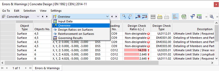
To check the specific design results of each surface, use the categories in the toolbar list. Each category has a set of tables assigned.
Design Ratios on Surfaces
Select the Design Ratios on Surfaces category (1). The design ratios of each surface are listed in five tables. The results are arranged by different criteria. Set the Design Ratios by Thickness table by clicking the tab (2).
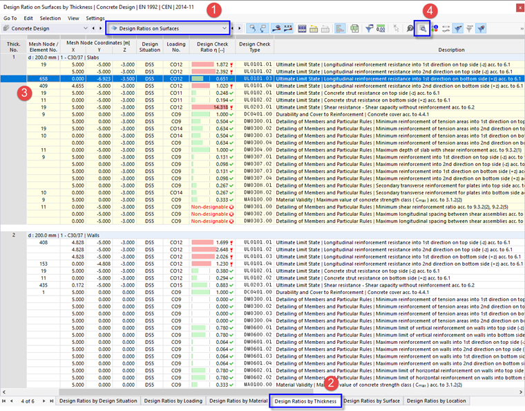
Slabs and walls were each defined by different thickness types. Therefore, the maximum design results of the slabs are listed in the first block (thickness no. 1) and those of the walls in the second block (thickness no. 2). Most of the red ratios can be explained by singularities (see Chapter Non-Designable Results).
In this table, the values listed in the 'Design Check Ratio' column represent the quotients of the required reinforcement areas and the provided reinforcement areas. The results include the design checks and the checks of detailing. The former are labelled as 'UL' check types, the latter as 'DM'. For example, 'UL0101.03' represents the check of the longitudinal reinforcement resistance according to EN 1992-1-1, 6.1 with reference to the primary direction at the bottom side of the slab (3). Select this line in the upper block (third line, mesh node no. 658).
To view the design details of this check, click the
![]() button on the table toolbar (4). A new window is opened.
button on the table toolbar (4). A new window is opened.
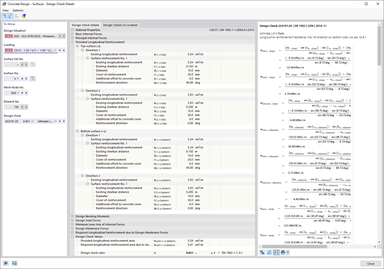
In this window, you can check all parameters of the design and the relevant equations. When you have finished, return to the tables by clicking Close.
Reinforcement on Surfaces
On the table toolbar, select the Reinforcement on Surfaces category (see the List of Categories for Design Results image). The reinforcement of each surface is listed in several tables by different criteria again. Set the Required Reinforcement by Surface table.
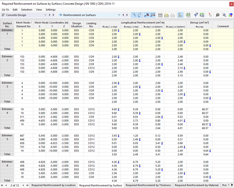
In this table, the extreme values of the required reinforcement are listed for every surface. The maximum areas of every reinforcement category are labelled by
![]() symbols. You can also examine which load combination requires the maximum reinforcement for each surface, surface side, and direction of reinforcement.
symbols. You can also examine which load combination requires the maximum reinforcement for each surface, surface side, and direction of reinforcement.
As before, you can check the details of the design in the 'Design Check Details' dialog box (see the Design Check Details image): Select a line and then click the
![]() button on the table toolbar.
button on the table toolbar.