2D
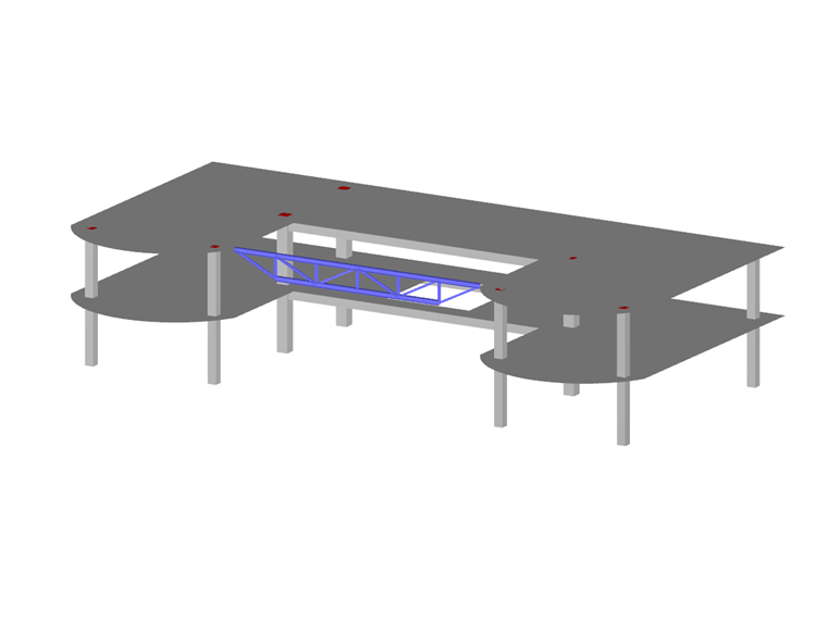
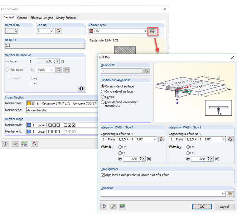
For modeling downstand and upstand beams, the "Rib" member type should be used. First, it is necessary to define the downstand beam as a rectangular cross-section and the "Rib". In the dialog box for the details of the rib, you can specify an effective width. From the rectangular beam and the effective width, a resulting T-shaped section is created.
For 2D models, there are no axial forces in the members and surfaces, but only the internal forces Vz, MT, and My or mx, my, mxy, vx, and vy.
Therefore, another calculation method than for the 3D model is used for ribs: a T-beam (defined from member cross-section and effective widths) is placed with its centroidal axis in the surface axis.
When changing the effective width, the stiffness of the system changes too!
3D
Also here, it is necessary to define the rectangular cross-section as a "Rib" member type with its effective width. However, the internal modeling is entirely different: the eccentricity is calculated from one-half the plate thickness and one-half the member height.
For 3D models, the rectangular cross-section defined as a rib is connected eccentrically (one-half the plate thickness + one-half the member height) to the surface. Thus, the stiffness of the system is defined. It does not change when changing the effective width; the deformation of the system remains the same, not the internal forces.
The axial forces of the T-beam are determined from the sum of the member axial forces and the surface axial forces integrated over the effective widths.
To determine bending moments, the axial forces as well as the moments of the T-beam are integrated over the effective width. The sum of the integral of the surface moment with the member moments yields a part of the T-beam moment. Also added are the integral of the T-beam axial forces and the member axial force, which are multiplied by the corresponding lever arm relative to the center of gravity of the T-beam.
The result is a beam moment relative to the T-shaped cross-section of the entire T-beam. With the rib internal forces, you can carry out a reinforced concrete design for the T-beam.
In the Display navigator, you can switch between the resulting internal forces of the rib and the member under "Results → Ribs".
The advantage of the more complex 3D rib model is that you can use it to consider the stiffnesses and internal forces more precisely.
If the integration width does not correspond to the effective width, you can adjust this for the design in the RF‑CONCRETE Members add-on module.