39 Results
View Results:
Sort by:

RFEM 6 offers the Aluminum Design add-on for the design of aluminum members. This article shows how class 4 sections are designed according to Eurocode 9 in the program.

The RX‑TIMBER stand-alone program offers you the option to optimize the lateral-torsional bracing. With this selection, the program iteratively determines the required minimum length of the lateral-torsional bracing.

Custom sections are often required in cold-formed steel design. In RFEM 6, the custom section can be created using one of the “Thin-Walled” sections available in the library. For other sections that do not meet any of the 14 available cold-formed shapes, the sections can be created and imported from the standalone program, RSECTION. For general information on AISI steel design in RFEM 6, refer to the Knowledge Base article provided at the end of the page.

Both the determination of natural vibrations and the response spectrum analysis are always performed on a linear system. If nonlinearities exist in the system, they are linearized and thus not taken into account. They are caused by, for example, tension members, nonlinear supports, or nonlinear hinges. This article shows how you can handle them in a dynamic analysis.

In order to be able to carry out a pushover analysis, it is necessary to transform the determined capacity curve into a simplified form. The N2 method is described in Eurocode EN 1998. This article should help to explain what a bilinearization according to the N2 method involves.

RF-CONCRETE Members for RFEM or CONCRETE for RSTAB propose an automatically created reinforcement to the user if the "Design the provided reinforcement" option is selected in Window 1.6 "Reinforcement".

The design of cold-formed steel members according to the AISI S100-16 is now available in RFEM 6. Design can be accessed by selecting “AISC 360” as the standard in the Steel Design add-on. “AISI S100” is then automatically selected for the cold-formed design (Image 01).

In the RF-/TIMBER Pro, RF-/TIMBER AWC, and RF-/TIMBER CSA add-on modules, you can consider the resulting deformation of a member or set of members. In addition to the local directions y and z, you have the option "R." This allows you to compare the total deflection of a girder to the limit values given in the standards.

To be able to evaluate the influence of local stability phenomena of slender structural components, RFEM 6 and RSTAB 9 provide you with the option of performing a linear critical load analysis on the cross-section level. The following article explains the basics of the calculation and the result interpretation.

The new RFEM software generation provides the option to perform stability design of tapered timber members in line with the equivalent member method. According to this method, the design can be performed if the guidelines of DIN 1052, Section E8.4.2 for variable cross-sections are met. In various technical literature, this method is also adopted for Eurocode 5. This article demonstrates how to use the equivalent member method for a tapered roof girder.

As an alternative to the equivalent member method, this article describes the possibility to determine the internal forces of a wall at risk of buckling according to the second-order analysis, taking imperfections into account, and to subsequently perform the cross-section design for bending and compression.

RFEM 6 offers the Aluminum Design add-on to design aluminum members for the ultimate and serviceability limit states according to Eurocode 9. In addition to this, you can perform design according to ADM 2020 (US Standard).

When a concrete slab is set upon the top flange, its effect is like a lateral support (composite construction), preventing problems of torsional buckling stability. If there is a negative distribution of the bending moment, the bottom flange is subjected to compression and the top flange is under tension. If the lateral support given by the stiffness of the web is insufficient, the angle between the bottom flange and the web intersection line is variable in this case so that there is a possibility of distortional buckling for the bottom flange.

The same structures are often needed in several projects, such as the purlin with columns and braces in this example. The dimensions can be changed directly in RFEM or RSTAB by shifting the nodes.

In the default setting, the cross-section class for each member and load case is determined automatically in the design modules. In the input window of the cross sections, however, the user can also specify the cross-section class manually; for example, if local buckling is excluded by the design.

In timber design, beams are often built from several timber elements. The individual elements can be connected with glue, nails, bolts, or dowels. A glued connection is to be assumed as rigid. In the case of dowel‑type fasteners, the joint is compliant (slip joint), and the cross‑section properties of the connected elements cannot be fully applied.

- 001819
- Design
- Aluminum Design for RFEM 6
-
- Aluminum Design for RSTAB 9
- Concrete Design for RFEM 6
- Concrete Design for RSTAB 9
- Steel Design for RFEM 6
- Steel Design for RSTAB 9
- Timber Design for RFEM 6
- Timber Design for RSTAB 9
- Concrete Structures
- Steel Structures
- Timber Structures
- Structural Analysis & Design
- Eurocode 0
- Eurocode 2
- Eurocode 3
- Eurocode 5
- Eurocode 9
- ADM
- ANSI/AISC 360
For the serviceability of a structure, the deformations must not exceed certain limit values. This article describes an example that shows how to analyze the deflection of members using Dlubal's design add-ons.

The following article describes a design using the equivalent member method according to [1] Section 6.3.2, performed on an example of a cross-laminated timber wall susceptible to buckling described in Part 1 of this article series. The buckling analysis will be performed as a compressive stress analysis with reduced compressive strength. For this, the instability factor kc is determined, which depends primarily on the component slenderness and the support type.

- 000487
- Modeling | Structure
- RFEM 5
-
- RF-STEEL 5
- RF-STEEL AISC 5
- RF-STEEL AS 5
- RF-STEEL BS 5
- RF-STEEL CSA 5
- RF-STEEL EC3 5
- RF-STEEL GB 5
- RF-STEEL HK 5
- RF-STEEL IS 5
- RF-STEEL NBR 5
- RF-STEEL NTC-DF 5
- RF-STEEL SANS 5
- RF-STEEL SIA 5
- RF-STEEL SP 5
- RF-ALUMINUM 5
- RF-ALUMINUM ADM 5
- RSTAB 8
- STEEL 8
- STEEL AISC 8
- STEEL AS 8
- STEEL BS 8
- STEEL CSA 8
- STEEL EC3 8
- STEEL GB 8
- STEEL HK 8
- STEEL IS 8
- STEEL NBR 8
- STEEL NTC-DF 8
- STEEL SANS 8
- STEEL SIA 8
- STEEL SP 8
- ALUMINUM 8
- ALUMINUM ADM 8
- Steel Structures
- Process Manufacturing Plants
- Stairway Structures
- Structural Analysis & Design
- Eurocode 3
- ANSI/AISC 360
- SIA 263
- IS 800
- BS 5950-1
- GB 50017
- CSA S16
- AS 4100
- SP 16.13330
- SANS 10162-1
- ABNT NBR 800
- ADM
The support conditions of a beam subjected to bending are essential for its resistance to lateral-torsional buckling. If, for example, a single-span beam is held laterally in the middle of the span, the deflection of the compressed flange can be prevented, and a two-wave eigenmode can be enforced. The critical lateral-torsional buckling moment is increased significantly by this additional measure. In the add-on modules for member design, different types of lateral supports on a member can be defined using the "Intermediate supports" input window.

In accordance with Sect. 6.6.3.1.1 and Clause 10.14.1.2 of ACI 318-19 and CSA A23.3-19, respectively, RFEM effectively takes into consideration concrete member and surface stiffness reduction for various element types. Available selection types include cracked and uncracked walls, flat plates and slabs, beams, and columns. The multiplier factors available within the program are taken directly from Table 6.6.3.1.1(a) and Table 10.14.1.2.

In the case of open cross-sections, the torsional load is removed mainly via secondary torsion, since the St. Venant torsional stiffness is low compared to the warping stiffness. Therefore, warping stiffeners in the cross-section are particularly interesting for the lateral-torsional buckling analysis, as they can significantly reduce the rotation. For this, end plates or welded stiffeners and sections are suitable.

The previous article, titled Lateral-Torsional Buckling in Timber Construction | Examples 1, explains the practical application for determining the critical bending moment Mcrit or the critical bending stress σcrit for a bending beam's lateral buckling using simple examples. In this article, the critical bending moment is determined by considering an elastic foundation resulting from a stiffening bracing.

Basically, you can design the structural components made of cross-laminated timber in the RF-LAMINATE add-on module. Since the design is a pure elastic stress analysis, it is necessary to additionally consider the stability issues (flexural buckling and lateral-torsional buckling).

Besides the standardized gamma method, you can display the semi-rigid composite beams also as a framework model.
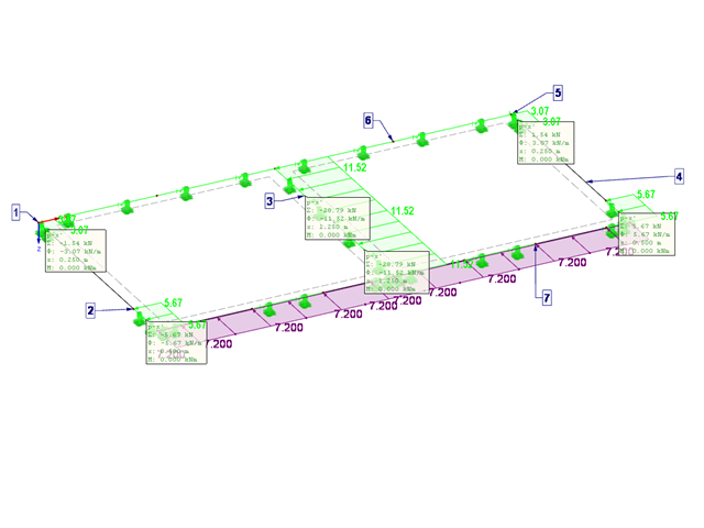
This article describes the design of timber panel walls due to generated horizontal loads.
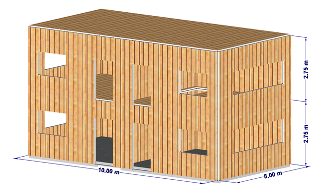
This article shows the effect of the different stiffnesses of the timber panel walls on the floor plan.
![Structural System and Cross-Section Dimensions According to [1]](/en/webimage/009153/2417271/01-en-png.png?mw=640&hash=c76563b459152b19c98197ea6ba342be89d9a5bc)
There are several options for calculating a semi-rigid composite beam. They differ primarily in the type of modeling. Whereas the Gamma method ensures simple modeling, additional efforts are required when using other methods (for example, shear analogy) for the modeling which are, however, offset by the much more flexible application compared to the Gamma method.

In RFEM 5 and RSTAB 8, you can design foundations according to EN 1992‑1‑1 and EN 1997‑1 in the RF‑/FOUNDATION Pro add‑on module.

The article titled Lateral-Torsional Buckling in Timber Construction | Theory explains the theoretical background for the analytical determination of the critical bending moment Mcrit or the critical bending stress σcrit for the lateral buckling of a bending beam. This article uses examples to verify the analytical solution with the result from the eigenvalue analysis.

- 001555
- Modeling | Loading
- RFEM 5
-
- RSTAB 8
- RF-TIMBER AWC 5
- TIMBER AWC 8
- RF-TIMBER CSA 5
- TIMBER CSA 8
- RF-TIMBER Pro 5
- TIMBER Pro 8
- RF-JOINTS Timber | Timber to Timber 5
- JOINTS Timber | Timber to Timber 8
- RF-JOINTS Timber | Steel to Timber 5
- JOINTS Timber | Steel to Timber 8
- RF-LIMITS 5
- LIMITS 8
- RF-LAMINATE 5
- Timber Structures
- Laminate and Sandwich Structures
- Structural Analysis & Design
- Finite Element Analysis
- Steel Connections
- Eurocode 0
- Eurocode 5
- ANSI/AISC 360
- SIA 260
- SIA 265
In addition to determining loads, some particularities concerning the load combinatorics in timber design have to be considered. Contrary to steel structures, where the largest loading results from all unfavorable actions, in timber construction, the strength values depend on the load duration and timber humidity. Special characteristics have to be considered as well for the serviceability limit state design. The following article discusses the effects on the design of wooden elements and how this is possible with RSTAB and RFEM.