195 Results
View Results:
Sort by:

The data exchange between RFEM 6 and Allplan can be done using various file formats. This article describes the data exchange of a determined surface reinforcement using the ASF interface. This allows you to display the RFEM reinforcement values as level curves or colored reinforcement images in Allplan.

The three types of moment frames (Ordinary, Intermediate, Special) are available in the Steel Design add-on of RFEM 6. The seismic design result according to AISC 341-22 is categorized into two sections: member requirements and connection requirements.

The three types of moment frames (Ordinary, Intermediate, Special) are available in the Steel Design add-on of RFEM 6. The seismic design result according to AISC 341-16 is categorized into two sections: member requirements and connection requirements.

Moment frame design according to AISC 341-16 is now possible in the Steel Design add-on of RFEM 6. The seismic design result is categorized into two sections: member requirements and connection requirements. This article covers the required strength of the connection. An example comparison of the results between RFEM and the AISC Seismic Design Manual [2] is presented.

The design of an Ordinary Concentrically Braced Frame (OCBF) and a Special Concentrically Braced Frame (SCBF) can be carried out in the Steel Design add-on of RFEM 6. The seismic design result according to AISC 341-16 and 341-22 is categorized into two sections: Member Requirements and Connection Requirements.

Creating a validation example for Computational Fluid Dynamics (CFD) is a critical step in ensuring the accuracy and reliability of simulation results. This process involves comparing the outcomes of CFD simulations with experimental or analytical data from real-world scenarios. The objective is to establish that the CFD model can faithfully replicate the physical phenomena it is intended to simulate. This guide outlines the essential steps in developing a validation example for CFD simulation, from selecting a suitable physical scenario to analyzing and comparing the results. By meticulously following these steps, engineers and researchers can enhance the credibility of their CFD models, paving the way for their effective application in diverse fields such as aerodynamics, aerospace, and environmental studies.

Wind direction plays a crucial role in shaping the outcomes of Computational Fluid Dynamics (CFD) simulations and the structural design of buildings and infrastructures. It is a determining factor in assessing how wind forces interact with structures, influencing the distribution of wind pressures, and consequently, the structural responses. Understanding the impact of wind direction is essential for developing designs that can withstand varying wind forces, ensuring the safety and durability of structures. Simplified, the wind direction helps in fine-tuning CFD simulations and guiding structural design principles for optimal performance and resilience against wind-induced effects.

Using an example of a steel fiber-reinforced concrete slab, this article describes how the use of different integration methods and of a different number of integration points affects the calculation result.

If you want to use a pure surface model, for example, when determining the internal forces and moments, but the structural component is still designed on the member model, you can take advantage of a result beam.

The modal relevance factor is a result of the linear stability analysis and qualitatively describes the degree of participation of individual members in a specific mode shape.

To be able to evaluate the influence of local stability phenomena of slender structural components, RFEM 6 and RSTAB 9 provide you with the option of performing a linear critical load analysis on the cross-section level. The following article explains the basics of the calculation and the result interpretation.

Large-scale models are models which contain multiple dimensional scales and thus are demanding on computational power. This article will show you how to simplify and optimize the calculation of such models with respect to the desired results.

In RFEM 6, the results for the FE mesh nodes are determined using the finite element method. For the distribution of internal forces, deformations, and stresses to be continuous, these nodal values are smoothed through an interpolation process. This article will introduce and compare the different types of smoothing that you can use for this purpose.

A new capability within RFEM 6 when designing concrete columns is being able to generate the moment interaction diagram according to the ACI 318-19 [1]. When designing reinforced concrete members, the moment interaction diagram is an essential tool. The moment interaction diagram represents the relationship between the bending moment and axial force at any given point along a reinforced member. Valuable information is shown visually like strength and how the concrete behaves under different loading conditions.

Spreadsheet programs like MS EXCEL are very popular with engineers because they allow you to simply automatize your calculations and quickly output the results. Therefore, combining MS EXCEL used as a graphical interface with Dlubal's WebService API is an obvious choice. By using the free xlwings library for Python, you can control EXCEL, and read and write values. The functionality is described in the following, using an example.

This article will show you the Building Model add-on, which has been enhanced with one important advantage: calculating the center of mass and center of rigidity.

The “Modal Analysis” add-on in RFEM 6 allows you to perform modal analysis of structural systems, thus determining natural vibration values such as natural frequencies, mode shapes, modal masses, and effective modal mass factors. These results can be used for vibration design, as well as for further dynamic analyses (for example, loading by a response spectrum).
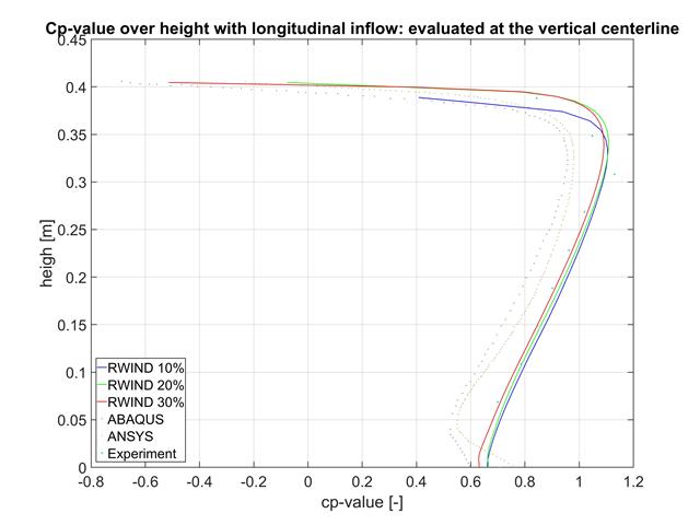
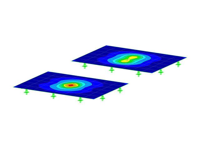
In this article, the results of RWIND, ABAQUS, and ANSYS are compared with a wind tunnel test using a geometrically simple structural model.
This article will introduce to you the “Surface Results Adjustments” in RFEM 6, corresponding to the "Average Region" function implemented in RFEM 5.

This article discusses the results of the geotechnical analysis and their graphical and tabular display in the RFEM 6 program.

The advantage of the RFEM 6 Steel Joints add-on is that you can analyze steel connections using an FE model for which the modeling runs fully automatically in the background. The input of the steel joint components that control the modeling can be done by defining the components manually, or by using the available templates in the library. The latter method is included in a previous Knowledge Base article titled “Defining Steel Joint Components Using the Library". The definition of parameters for the design of steel joints is the topic of the Knowledge Base article “Designing Steel Joints in RFEM 6".

Structures in RFEM 6 can be saved as blocks and reused in other RFEM files. The advantage of dynamic blocks with respect to non-dynamic blocks is that they allow interactive modifications of the structural parameters as a result of modified input variables. One example is the possibility to add structural elements by changing only the number of bays as an input variable. This article will demonstrate the aforementioned possibility for dynamic blocks that are created by scripting.

In RFEM 6, seismic analysis can be done by using the Modal Analysis and the Response Spectrum Analysis add-ons. Once the spectral analysis has been performed, it is possible to use the Building Model add-on to display story actions, interstory drifts, and forces in shear walls.

Steel has poor thermal properties in terms of fire resistance. The thermal expansion for increasing temperature is very high compared to that of other building materials, and might result in effects that were not present in the design at normal temperature due to restraint in the component. As temperature increases, steel ductility increases, whereas its strength decreases. Since steel loses 50% of its strength at temperature of 600 °C, it is important to protect components against fire effects. In the case of protected steel components, the fire resistance duration can be increased due to the improved heating behavior.

This article compares the design to the one in the referenced article: Design of Concrete Columns Subjected to Axial Compression with RF-CONCRETE Members. It is, therefore, about taking exactly the same theoretical application carried out in RF-CONCRETE Members and reproducing it in RF-CONCRETE Columns. Thus, the objective is to compare the different input parameters and the results obtained by the two add-on modules for the design of column-like concrete members.

You can use the selection options in the printout report to receive the detail results (in short or long form) to illustrate the individual buckling modes with the relevant buckling analysis.

The add-on modules for designing structural member components according to national, European, and international standards also show design results in addition to numerical output in tables graphically, as diagrams displayed on the framework.

In RFEM, it is possible to display the resultant of a section or release. This article explains which part of the sectional area is affected. The easiest way would be to refer the resultant to a cut face of the surface. However, since a section may run through several surfaces with different local coordinate systems, determination by means of a cut face is not possible.

In RF-/FOUNDATION Pro, the foundation design requires the definition of the corresponding loading (load cases, load combinations, or result combinations) for different design situations (STR, GEO, UPL, or EQU).

The dialog box for editing load or result combinations is a non-modal dialog box. This means that after you open this dialog box, you can edit the combinations outside the dialog box as well. For manually defining or editing a combination, a separate dialog box can be opened parallel to the "Edit load cases and combinations" dialog box.