44 Results
View Results:
Sort by:
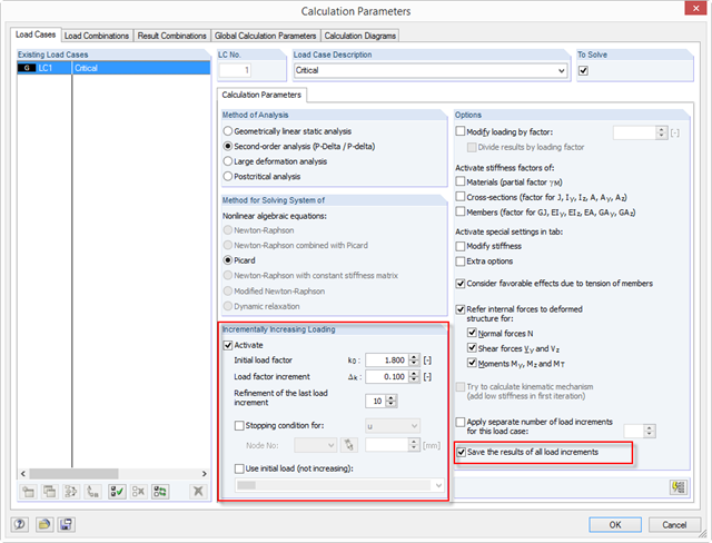
With RFEM 5.04, there are new options for the system analysis (critical load factors) of load cases and load combinations in the calculation parameters of the RF‑STABILITY add‑on module: ~ The load increment is not closed due to stability problems, but optionally also due to predetermined deformation limits. ~ The calculation method is applicable to all nonlinear calculations. ~ You can define an initial load (LC/CO) that is not increased (for example, self-weight). ~ The "Refinement of the last load increment" option provides an efficient option to determine the critical load factor as precisely as possible.
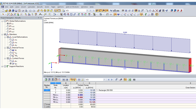
If a model should contain members with elastic foundations, the contact forces and moments are displayed in numerical form in the result windows. The graphical display of results is specified by the "Members" entry in the Results Navigator.
The last part of my post deals with the consideration of forces resulting from the imposed deformation of a cross‑laminated timber plate when designing a structure with imposed loads.
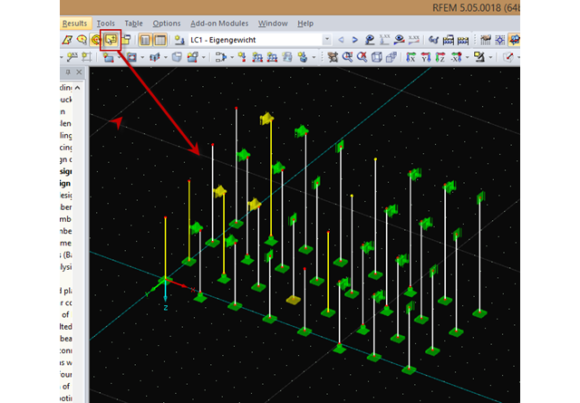
You can select an object in RFEM or RSTAB by simply clicking it. However, only the last object clicked will stay selected. In order to select several objects at a time, press the Control key while clicking. Since this procedure is not always possible, you can use the "Add to Selection" function in the toolbar or in the "Edit" → "Select" menu.

In the following example, the stability analysis of a steel frame can be performed according to the General Method in compliance with EN 1993‑1‑1, Sect. 6.3.4 in the RF‑/STEEL EC3 add-on module. The first of my three posts shows the determination of the critical load factor for design loads required by the design concept, which reaches the elastic critical buckling load with deformations from the main framework plane.
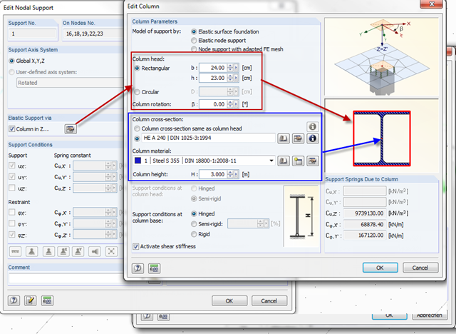
In RFEM 5.06 and RSTAB 8.06, the nodal support type "Elastic Support via Column in Z…" has been extended so you can use an individual cross‑section as a column cross‑section; for example, HEA from the cross‑section library. The column's cross-section is used to calculate the elastic support.
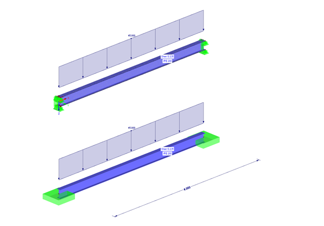
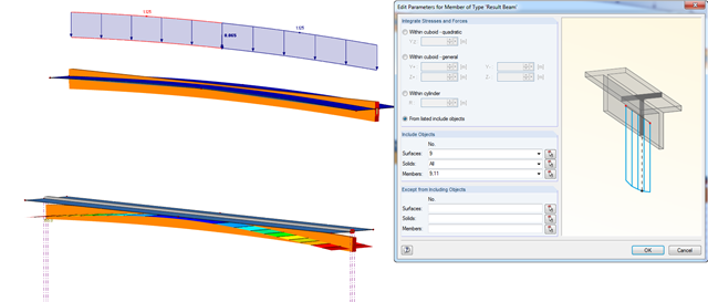
The following example presents a comparison between a shell model and a simple member model performed in RFEM. In the case of the shell model, there is a beam suspended in surfaces, which is modeled with restraints on both sides due to the boundary conditions. This is a statically indeterminate system that forms plastic hinges when overloaded. The comparison is carried out on a member model that has the same boundary conditions as the shell model.

The following article describes the design of a single-span beam subjected to bending and compression, which is performed according to EN 1993‑1‑1 in the RF-/STEEL EC3 add-on module. Since the beam is modeled with a tapered cross-section and thus it is not a uniform structural component, the design must be performed either according to General Method in compliance with Sect. 6.3.4 of EN 1993‑1‑1, or according to the second-order analysis. Both options will be explained and compared, and for the calculation according to the second-order analysis, there is an additional design format using Partial Internal Forces Method (PIFM) available. Therefore, the design is divided into three steps: design according to Sect. 6.3.4 of EN 1993‑1‑1 (General Method), design according to the second‑order analysis, elastic (warping torsion analysis), design according to the second‑order analysis, plastic (warping torsion analysis and Partial Internal Forces Method).
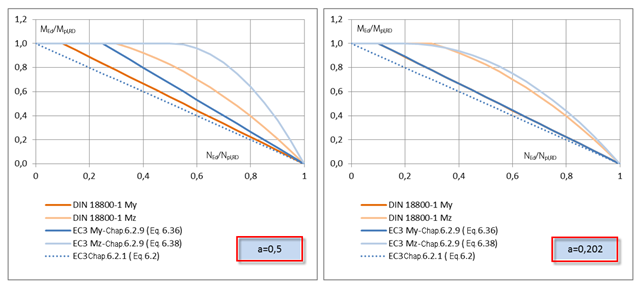
RF-/STEEL EC3 allows you to perform plastic design checks of cross‑sections according to EN 1993‑1‑1, Sec. 6.2. You should pay attention to the interaction of loading due to the bending and axial force for I‑sections, which is regulated in Sec. 6.2.9.1.

Prior to the analysis of steel cross‑sections, the cross‑sections are classified according to EN 1993‑1‑1, Sec. 5.5, with respect to their resistance and rotation capacity. Thus, the individual cross-section parts are analyzed and assigned to Classes 1 to 4. The cross-section classes are determined subsequently and usually assigned to the highest class of the cross-section parts. If plastic resistance is to be applied to further design of cross-sections of Class 1 and Class 2, you can analyze the elastic resistance of cross-sections as of Class 3. In the case of cross-sections of Class 4, local buckling occurs even before reaching the elastic moment. In order to take this effect into account, you can use effective widths. This article describes the calculation of the effective cross-section properties in more detail.
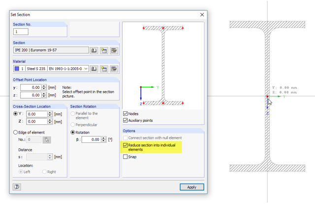
SHAPE‑THIN cross‑section properties software determines the effective section properties of thin‑walled cross‑sections according to Eurocode 3 and Eurocode 9. Alternatively, the program allows plastic design of general cross‑sections according to the Simplex Method. In this process, plastic cross-section reserves are iteratively calculated for elastically determined internal forces. The following example describes the effective cross-section properties in the notching area of a rolled I-section. Afterwards, the results are compared with the plastic analysis.
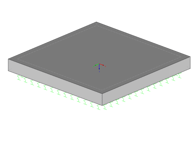
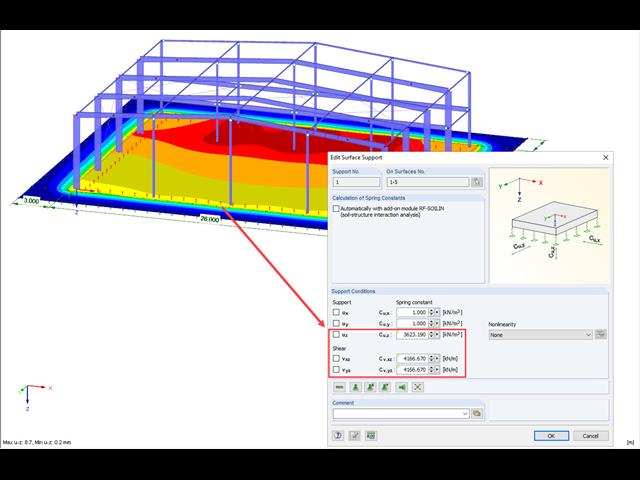
A foundation is usually created in RFEM using the subgrade reaction modulus method. The reason for this is the relatively easy and straightforward manageability. Also, no iterative calculations are necessary and the computing time is relatively short. The subgrade reaction means that, for example, a foundation plate is loaded flat elastically.
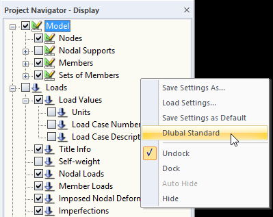
When you receive an RFEM or RSTAB file for further processing, the structures will be displayed in the program using the display settings of the last editor. If the settings do not correspond to your requirements, you can simply right‑click the empty area in Project Navigator - Display and select "Dlubal Standard". This returns the settings to the default values.
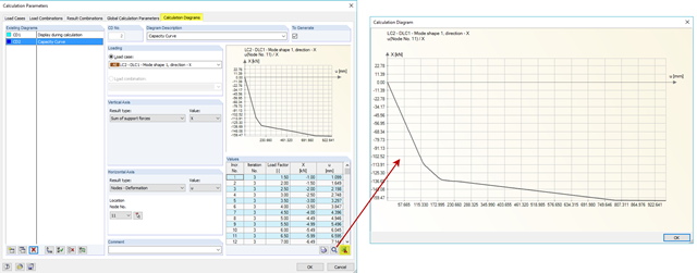
Pushover analysis is a nonlinear structural calculation for seismic analysis of structures. The load pattern is inferred from the dynamic calculation of equivalent loads. These loads are increased incrementally until global failure of the structure occurs. The nonlinear behaviour of a building is usually represented by using plastic hinges.
![Time-Dependent Settlement Components [2]](/en/webimage/009673/2419908/01-en-png-png.png?mw=640&hash=5e657e3feb5c1bb6d21727468dd85d91e1c9f29f)
For the serviceability limit state design according to Section 6.6 of Eurocode EN 1997‑1, settlement has to be calculated for spread foundations. RF-/FOUNDATION Pro allows you to perform the settlement calculation for a single foundation. For this, you can chose between an elastic and a solid foundation. By defining a soil profile, it is possible to consider several soil layers under the foundation base. The results of the settlement, foundation tilting, and vertical soil contact stress distribution are displayed graphically and in tables to provide a quick and clear overview of the calculation performed. In addition to the design of the foundation settlement in RF-/FOUNDATION Pro, the structural analysis determines the representative spring constants for the support and can be exported to the structural model of RFEM or RSTAB.

Basically, you can design the structural components made of cross-laminated timber in the RF-LAMINATE add-on module. Since the design is a pure elastic stress analysis, it is necessary to additionally consider the stability issues (flexural buckling and lateral-torsional buckling).
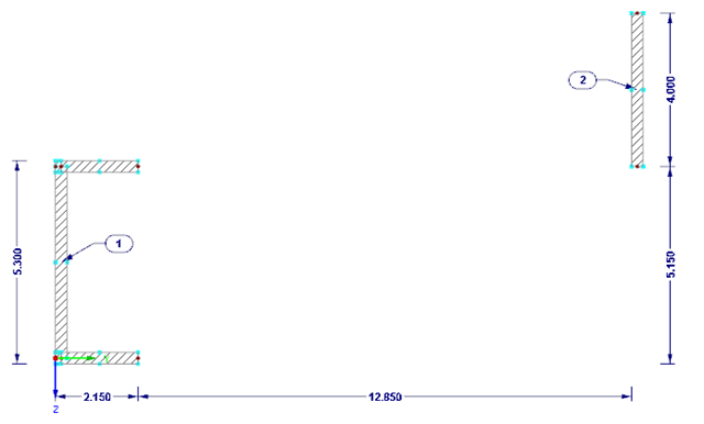
Buildings must be designed and dimensioned in the way that both vertical and horizontal loads are conducted safely and without large deformations in the building. Examples of horizontal loads are wind, unintentional inclination, earthquake, and a blast.
A previous article presented different variants of surface elastic foundations in addition to the traditional subgrade reaction modulus method. The following article describes another method for surface foundation. This method considers the adjacent ground areas by means of a foundation overlap. In this case, foundation parameters refer to the continuing works by Pasternak and Barwaschow.
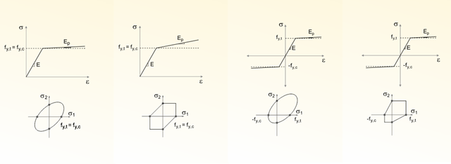
One of my earlier articles described the Isotropic Nonlinear Elastic material model. However, many materials do not have purely symmetrical nonlinear material behavior. In this regard, the yield laws according to von Mises, Drucker-Prager and Mohr-Coulomb mentioned in this previous article are also limited to the yield surface in the principal stress space.
Orthotropic material laws are used wherever materials are arranged according to their loading. Examples include fiber-reinforced plastics, trapezoidal sheets, reinforced concrete, and timber.

When designing steel columns or steel beams, it is usually necessary to carry out cross-section design and stability analysis. While the cross-section design can usually be performed without giving further details, the stability analysis requires further user-defined entries. To a certain extent, the member is cut out of the structure; therefore, the support conditions have to be specified. This is particularly important when determining the ideal elastic critical moment Mcr. Furthermore, it is necessary to define the correct effective lengths Lcr. These are required for the internal calculation of slenderness ratios.

RFEM and RSTAB offer different options to model bored piles. One option is to display bored piles as single-valued supports or hinged columns. Another option is realistic modeling while taking the soil into account by means of applying a member elastic foundation. The two following examples will describe it in detail. However, pile base resistance, skin friction, and soil layers are not considered in this technical article.
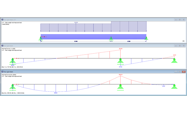
The following article describes designing a two-span beam subjected to bending by means of the RF-/STEEL EC3 add-on module according to EN 1993-1-1. The global stability failure will be excluded due to sufficient stabilizing measures.

When designing a steel cross-section according to Eurocode 3, it is important to assign the cross-section to one of the four cross-section classes. Classes 1 and 2 allow for a plastic design; classes 3 and 4 are only for elastic design. In addition to the resistance of the cross-section, the structural component's sufficient stability has to be analyzed.

The elastic deformations of a structural component due to a load are based on Hooke's law, which describes a linear stress-strain relation. They are reversible: After the relief, the component returns to its original shape. However, plastic deformations lead to irreversible deformations. The plastic strains are usually considerably larger than the elastic deformations. For plastic stresses of ductile materials such as steel, yielding effects occur where the increase in deformation is accompanied by hardening. They lead to permanent deformations - and in extreme cases to the destruction of the structural component.

In this article, representations of a blast scenario of a remote detonation performed in RF-DYNAM Pro - Forced Vibrations are shown, and the effects are compared in the linear time history analysis.

The previous article, titled Lateral-Torsional Buckling in Timber Construction | Examples 1, explains the practical application for determining the critical bending moment Mcrit or the critical bending stress σcrit for a bending beam's lateral buckling using simple examples. In this article, the critical bending moment is determined by considering an elastic foundation resulting from a stiffening bracing.
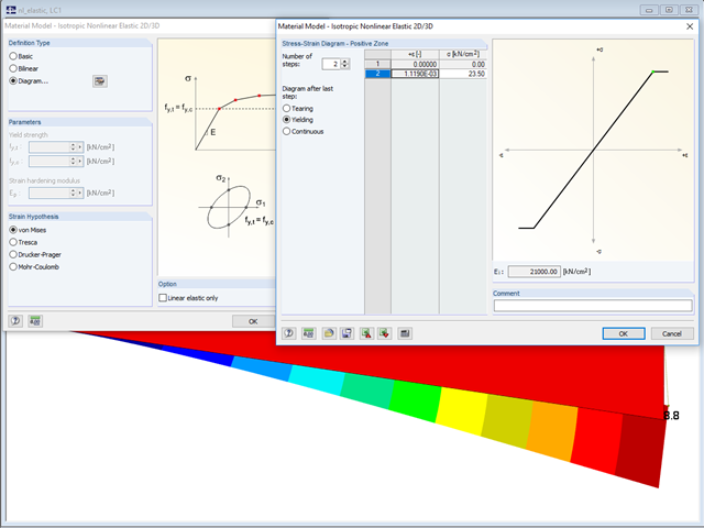
In the "Material Model - Isotropic Nonlinear Elastic" window, you can select the yield laws according to the von Mises, Tresca, Drucker-Prager, and Mohr-Coulomb yield rules. This makes it possible to describe the elasto-plastic material behavior. The yield function depends on the principal stresses or the invariants of a stress tensor. The criteria apply to 2D and 3D material models.
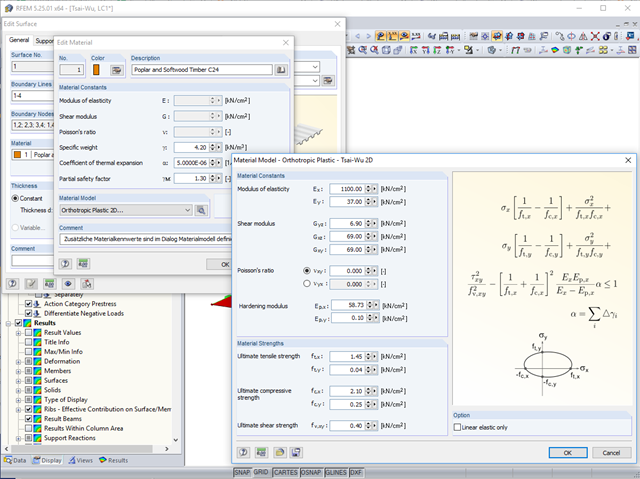
In RFEM, orthotropic plastic analyses using the Tsai‑Wu plasticity criterion have been possible for quite some time now. The hardening modulus Ep,x or Ep,y can be used to consider the hardening of the material during the iterative calculation.
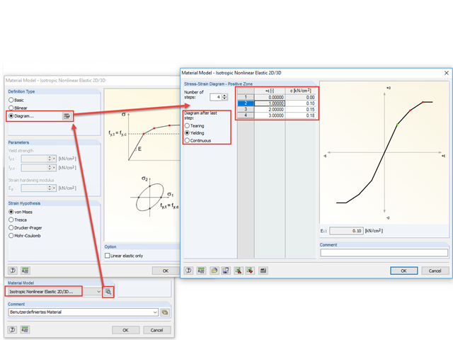
With the nonlinear elastic material model in RFEM 5, you can calculate and carry out a stress analysis of surfaces and solids with nonlinear material properties.