61 Results
View Results:
Sort by:

This article shows how to create cross-sections using DXF files.

RFEM 6 offers the Aluminum Design add-on for the design of aluminum members. This article shows how class 4 sections are designed according to Eurocode 9 in the program.

This article will show you the design of cold-formed steel cross-sections according to EN 1993-1-3, Section 6.1.6 in RFEM 6. Since the topic is still under development, the currently available options will be presented.

The stand-alone program RSECTION is at your disposal for determining section properties and performing stress analysis for thin-walled and massive cross-sections. The program can be connected to both RFEM and RSTAB so that sections from RSECTION are also available in the RFEM and RSTAB library. Likewise, internal forces from RFEM and RSTAB can be imported into RSECTION.

You can use the stand-alone program RSECTION to determine the section properties for any thin-walled and massive cross-sections, as well as to perform a stress analysis. The previous Knowledge Base article titled "Graphical/Tabular Creation of User-defined Cross-sections in RSECTION 1" discussed the basis of defining cross-sections in the program. This article, on the other hand, is a summary of how to determine the section properties and perform a stress analysis.

RSECTION 1 is a stand-alone program for determining section properties for both thin-walled and massive cross-sections, as well as for performing a stress analysis. In addition, the program can be connected to both RFEM and RSTAB: sections from RSECTION are available in the RFEM/RSTAB libraries, and internal forces from RFEM/RSTAB can be imported into RSECTION.

The design of cross-sections according to Eurocode 3 is based on the classification of the cross-section to be designed in terms of classes determined by the standard. The classification of cross-sections is important, since it determines the limits of resistance and rotation capacity due to local buckling of cross-section parts.

The new RFEM software generation provides the option to perform stability design of tapered timber members in line with the equivalent member method. According to this method, the design can be performed if the guidelines of DIN 1052, Section E8.4.2 for variable cross-sections are met. In various technical literature, this method is also adopted for Eurocode 5. This article demonstrates how to use the equivalent member method for a tapered roof girder.

Rolled sections, the most common cross‑section type in RFEM and RSTAB, can also have user‑defined parameters. To do this, select the cross‑section to be modified in the cross‑section library and click the [Parametric Input...] button.

In RFEM and RSTAB, parametrization provides you with many options, especially for recurring structural elements. Within the parametrization tool, you can access the internal values of a model; for example, the values of a selected cross‑section. The following example shows how this can work.
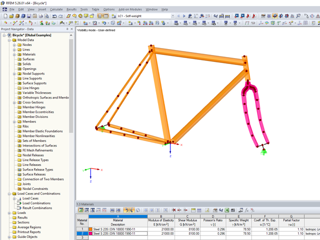
In RFEM and RSTAB, you can simulate extensive complex models from different materials in one computing environment.

The number of National Annexes for Eurocode 2 with regard to the design of reinforced concrete cross-sections has been extended since SHAPE-MASSIVE 6.54. Therefore, the following NAs of EN 1992-1-1:2004 + AC:2010 are available:

A member's boundary conditions decisively influence the elastic critical moment for lateral-torsional buckling Mcr. The program uses a planar model with four degrees of freedom for its determination. The corresponding coefficients kz and kw can be defined individually for standard-compliant cross-sections. This allows you to describe the degrees of freedom available at both member ends due to the support conditions.
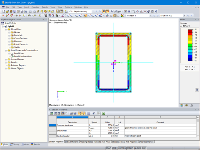
The material allocation for hybrid SHAPE‑THIN cross‑sections can be selected easily in RFEM and RSTAB. The prerequisite for this is the allocation of different materials to the cross‑section elements in SHAPE‑THIN.

In the age of BIM, data exchange between the various disciplines of structural engineering is becoming increasingly important. Since each software has its own specifications with regard to the description of cross-sections and materials, RFEM and RSTAB offer a conversion table (mapping file).

The RF‑/STEEL EC3 add-on module can perform the design of fillet welds for all parametric, welded cross-sections of the cross-section library. For this, the option must be activated in the detail settings of the module. As an alternative, you can also use a surface model for the design.

The German Annex to EN 1992‑1‑1, the National Addition NCI to Article 9.2.1.2 (2), recommends to dispose the tension reinforcement in the flange plate of T‑beam cross‑sections on a maximum of one width corresponding to the half of a computed effective flange width beff,i according to Expression (5,7a).

General thin-walled cross-sections often have asymmetrical geometries. The principal axes of such sections are then not parallel to the horizontally and vertically aligned axes Y and Z. When determining the cross-section properties, the angle α between the center-of-gravity axis y and the principal axis u is determined in addition to the principal axis-related moments of inertia.
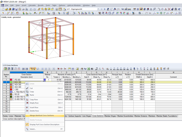
When modeling more complex structures with an increased degree of repetition, identical material and cross-section definitions often occur.

In the "Edit Load Cases and Combinations" dialog box, you can combine different load cases in one load combination under the "Load Combinations" tab.

You can use the "Free Circular Load" option in RFEM to apply a partial uplift force to a cone‑shaped floor slab. It can be defined as linearly variable. The definition of center C and the outer boundary R can be specified easily, using the select function.

For a quick overview of the cross‑sections used, you can show the members in color sorted by cross‑section. Use the right mouse button in the work window to select "Colors in Graphics According to" → "Cross -Sections" from the shortcut menu. In the current program versions, you can use a panel with an editable color scale for this.
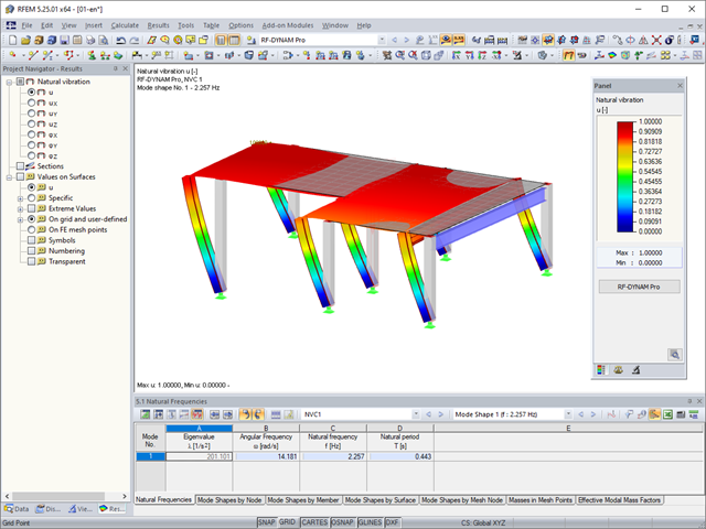
In RFEM, you can modify stiffnesses for materials, cross-sections, members, load cases, and load combinations in many places. There are two options in RF‑DYNAM Pro for considering these modifications when determining the natural frequencies.

In timber design, beams are often built from several timber elements. The individual elements can be connected with glue, nails, bolts, or dowels. A glued connection is to be assumed as rigid. In the case of dowel‑type fasteners, the joint is compliant (slip joint), and the cross‑section properties of the connected elements cannot be fully applied.

The RF‑/STEEL EC3 add-on module automatically transfers the buckling line to be used for the flexural buckling analysis for a cross-section from the cross-section properties. The assignment of the buckling line can be adjusted manually in the module input for general cross-sections in particular, as well as for special cases.

In RFEM 5 and RSTAB 8, it is possible to assign nonlinearities to member hinges. In addition to the nonlinearities "Fixed if" and "Partial activity", you can select "Diagram". If you select the "Diagram" option, you have to specify the according settings for the activity of the member hinge. For the individual definition points, it is necessary to specify the abscissa and ordinate values (deformations or rotations and the according internal forces) that define the hinge.

In the case of open cross-sections, the torsional load is removed mainly via secondary torsion, since the St. Venant torsional stiffness is low compared to the warping stiffness. Therefore, warping stiffeners in the cross-section are particularly interesting for the lateral-torsional buckling analysis, as they can significantly reduce the rotation. For this, end plates or welded stiffeners and sections are suitable.
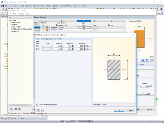
In the course of a reasonable pre-dimensioning of cross-sections, you can optimize the cross-sections of the corresponding section series in the RF‑/TIMBER Pro add-on module.

When optimizing cross-sections in the add-on modules, you can also select arbitrarily defined cross-section favorites lists - in addition to the cross-sections from the same cross-section series as the original cross-section.

The classification of cross-sections according to EN 1993-1-1 using Table 5.2 is a simple method for designing the local buckling of cross-section parts. For cross-sections of cross-section class 4, it is then necessary to determine the effective cross-section properties according to EN 1993-1-5 in order to consider the influence of local buckling in the ultimate limit state designs.