66 Results
View Results:
Sort by:

When calculating regular structures, data input is often not complicated but time-consuming. Input automation can save valuable time. The task described in the present article is to consider the stories of a house as single construction stages. Data is entered using a C# program so that the user does not have to enter the elements of the individual floors manually.

Our webservice offers users the opportunity to communicate with RFEM 6 and RSTAB 9 using various programming languages. Dlubal's high-level functions (HLFs) allow you to expand and simplify the WebService's functionality. In line with RFEM 6 and RSTAB 9, using our WebService makes the engineer's work easier and faster. Check it out now! This tutorial shows you how to use the C# library by means of a simple example.

As you may already know, RFEM 6 offers you the possibility to consider material nonlinearities. This article explains how to determine internal forces in slabs modeled with nonlinear material.
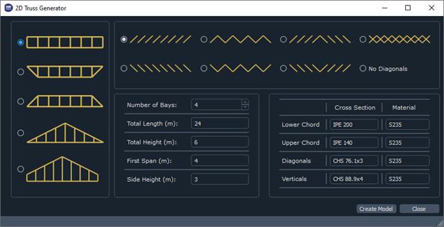
The recently introduced Webservices gives users the ability to communicate with RFEM 6 using their programming language of choice. This feature is enhanced with our High Level Functions (HLF) Library. The libraries are available for Python, JavaScript, and C#. This article looks at a practical use case of programming a 2D Truss Generator with Python. "Learning by doing," as the saying goes.

A standard scenario in timber member construction is the ability to connect smaller members by means of bearing on a larger girder member. Additionally, member end conditions may include a similar situation where the beam is bearing on a support type. In either scenario, the beam must be designed to consider the bearing capacity perpendicular to the grain according to NDS 2018 Sec. 3.10.2 and CSA O86:19 Clauses 6.5.6 and 7.5.9. In general structural design software, it is typically not possible to carry out this full design check, as the bearing area is unknown. However, in the new generation RFEM 6 and Timber Design add-on, the added 'design supports' feature now allows users to comply with the NDS and CSA bearing perpendicular to the grain design checks.

You can use the stand-alone program RSECTION to determine the section properties for any thin-walled and massive cross-sections, as well as to perform a stress analysis. The previous Knowledge Base article titled "Graphical/Tabular Creation of User-defined Cross-sections in RSECTION 1" discussed the basis of defining cross-sections in the program. This article, on the other hand, is a summary of how to determine the section properties and perform a stress analysis.

With the release of the structural analysis programs RFEM 6, RSTAB 9, RSECTION 1, and RWIND 2, Dlubal Software introduces a new generation of structural analysis programs. True to the motto "Structural analysis that is fun ...", the program provides users with universal tools with which they can meet all the requirements in structural engineering. Find out more about the latest developments at Dlubal Software in this article.

RSECTION 1 is a stand-alone program for determining section properties for both thin-walled and massive cross-sections, as well as for performing a stress analysis. In addition, the program can be connected to both RFEM and RSTAB: sections from RSECTION are available in the RFEM/RSTAB libraries, and internal forces from RFEM/RSTAB can be imported into RSECTION.

The new generation of RFEM software is an intuitive, powerful, and easy-to-handle 3D FEA program that meets all the latest demands in modeling, calculation, and structural design. The modern design concept, as well as the introduction of new features, make the program even more innovative and user-friendly. The main differences between RFEM 6 and its previous version, RFEM 5, are discussed in the following text.

Rolled sections, the most common cross‑section type in RFEM and RSTAB, can also have user‑defined parameters. To do this, select the cross‑section to be modified in the cross‑section library and click the [Parametric Input...] button.
The tools arrangement in the workplace can make your work fast and efficient.

Foundations including dimensions can be saved as a template in a user-defined database.

In RFEM 5 as well as RSTAB 8 in RF-/FOUNDATION Pro, you can save the foundation dimensions for all five foundation types as foundation templates in a user-defined database and use them later in other models.

You can make various settings in order to achieve a clearly‑arranged display of the result values. For example, some users may not want the white background in text bubbles. You can adjust the background in "Display Properties" using the Transparent and Background color option.

To work even more efficiently, RF‑GLASS allows you to create and save different, user‑defined layer structures that can be reimported later or loaded in another project.
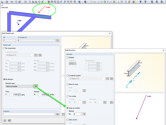
RFEM and RSTAB provide various options for entering nodal loads. These implemented features allow the user to define the nodal loads in relation to different components in space.
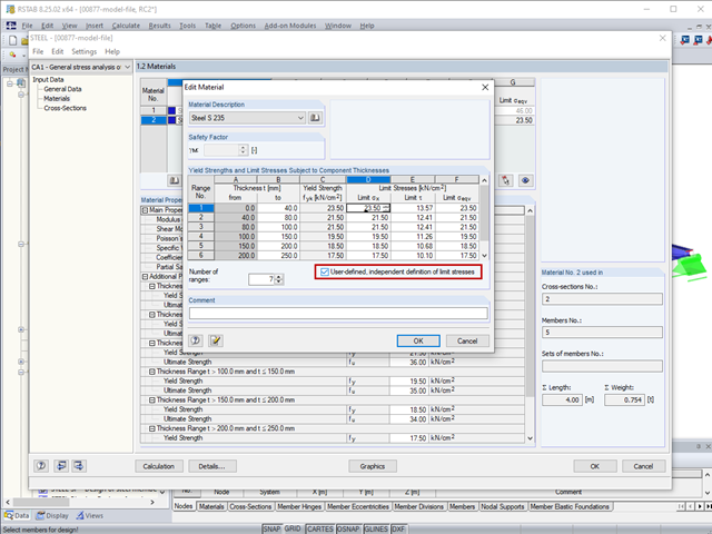
The limit stresses in RF‑/STEEL can be user-defined for each thickness range.

Supports contributing to a load reduction only under compression or tension can be defined as nonlinear supports in RFEM and RSTAB. It is not always easy for the user to select the correct nonlinearity for "failure under tension" or "failure under compression".

In RF‑/FOUNDATION Pro, the available reinforcing steel diameters can be adjusted by the user. The adjustment of the available rebar diameters works similarly to the same function in the RF‑/CONCRETE (Members) and RF‑/CONCRETE Columns add‑on modules.

RFEM and RSTAB offer many display options in the Display Navigator. They can be completely different, depending on their function. You often have to click several times to make certain changes. If you want to optimize your work, you can create user‑defined views. In these views, you can save all specified settings. The following example illustrates this principle.

In RF-/FOUNDATION Pro, the user can freely select the proportion of the relieving soil pressure by means of the factor kred.

In the default setting, the cross-section class for each member and load case is determined automatically in the design modules. In the input window of the cross sections, however, the user can also specify the cross-section class manually; for example, if local buckling is excluded by the design.
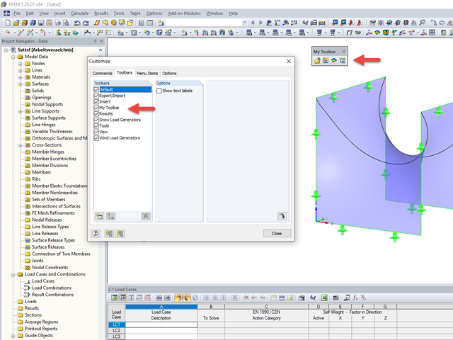
An individual user‑defined workspace can increase your productivity and make your daily work easier. This is why many users take the opportunity to adjust the toolbars in RFEM and RSTAB and to create their own toolbars containing the most frequently used commands.

In RF‑/CONCRETE Columns, different methods are available for defining the minimum longitudinal reinforcement. The minimum reinforcement can be selected according to the design standard used and/or specified by the user.
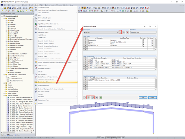
In RFEM and RSTAB, you can define a user-defined combination scheme. This can be helpful if a desired combination scheme cannot be created from a standard. In such cases, you can export the created load cases to Excel, create the scheme there, then import them to RFEM or RSTAB.

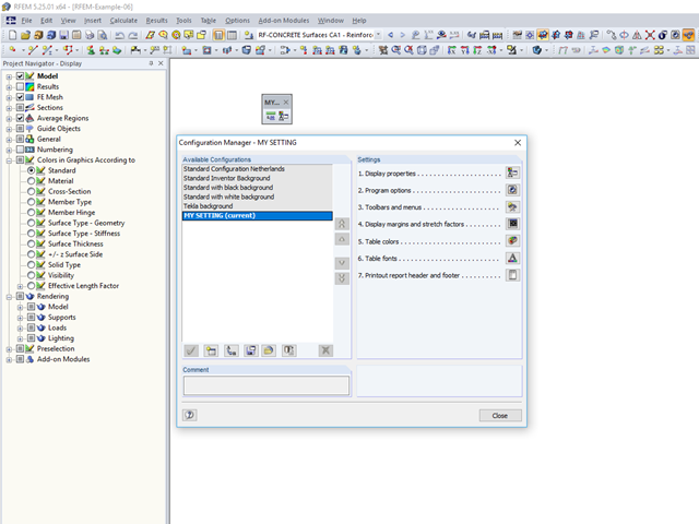
In RFEM, RSTAB, and SHAPE-THIN, you can create user-defined print templates ("Printout Report Template") and printout headers ("Report Headers"). These templates can also be transferred to other computers and used there.

Before creating a structural model, every user gives thought to the boundary parameters of the system and how best to represent the model. Special attention should be paid to the orientation of the global coordinate system. In engineering, the global Z‑axis is usually oriented downwards (in the direction of the dead load), while it tends to be upwards in architecture. These differences can often lead to complications during modeling; for example, when you replace global models or DXF layers.
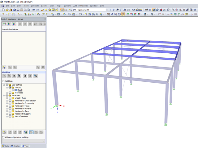
User-defined visibilities facilitate program handling. Once created, any model groups can be quickly hidden or shown. This facilitates, among other things, the analysis of the results in larger 3D structures, as well as the creation of the report. When changing the geometry, the existing visibilities may have to be updated.

RF-CONCRETE Members for RFEM or CONCRETE for RSTAB propose an automatically created reinforcement to the user if the "Design the provided reinforcement" option is selected in Window 1.6 "Reinforcement".
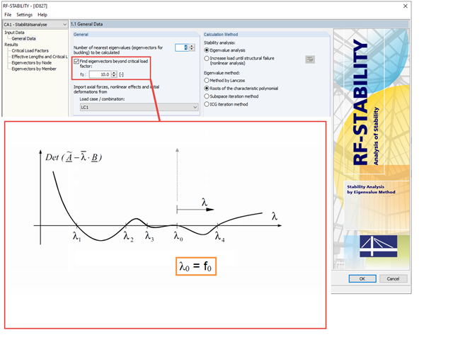
The function, which is also known as shifting, allows you to calculate critical load factors beyond a user‑defined initial value. Determination of the critical load factors is usually done from the smallest to the greatest critical load factor.