244 Results
View Results:
Sort by:
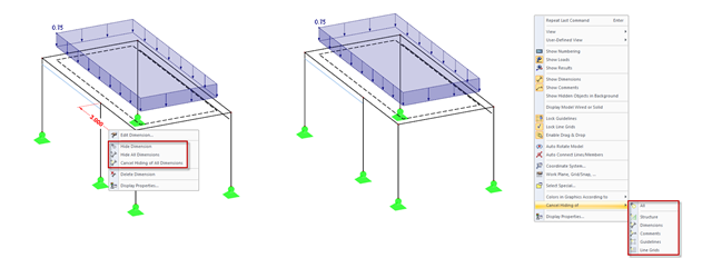
In addition to the options of Project Navigator - Display, you can modify the visibility of structures (members, surfaces, and so on) and guide objects (dimensions, comments, guidelines, and so on) in the menu and toolbar using the shortcut menus.

Using the Timber Design add-on, timber column design is possible according to the 2018 NDS standard ASD method. Accurately calculating timber member compressive capacity and adjustment factors is important for safety considerations and design. The following article will verify the maximum critical buckling strength calculated by the Timber Design add-on using step-by-step analytical equations as per the NDS 2018 standard including the compressive adjustment factors, adjusted compressive design value, and final design ratio.

A new capability within RFEM 6 when designing concrete columns is being able to generate the moment interaction diagram according to the ACI 318-19 [1]. When designing reinforced concrete members, the moment interaction diagram is an essential tool. The moment interaction diagram represents the relationship between the bending moment and axial force at any given point along a reinforced member. Valuable information is shown visually like strength and how the concrete behaves under different loading conditions.
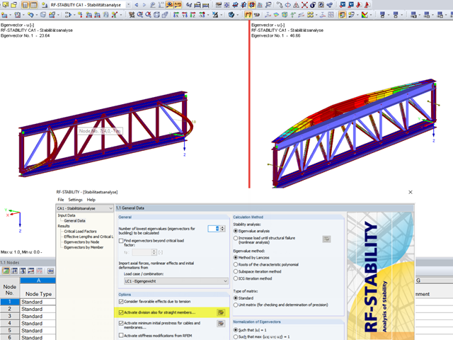
When analyzing structural elements susceptible to buckling by using the modules RF‑STABILITY (for RFEM) or RSBUCK (for RSTAB), it might be necessary to activate the internal division of members.
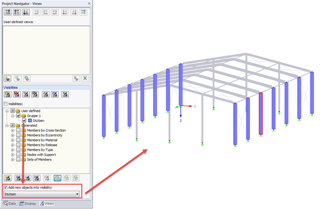
If new objects are created in an existing visibility, they are hidden immediately, since they do not comply with the particular visibility. However, if you want to display the new objects immediately in an existing visibility, for example when creating a new member, simply select the "Add new objects to visibility" check box.

In RF‑/FOUNDATION Pro, the available reinforcing steel diameters can be adjusted by the user. The adjustment of the available rebar diameters works similarly to the same function in the RF‑/CONCRETE (Members) and RF‑/CONCRETE Columns add‑on modules.
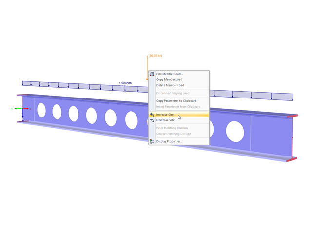
The display size of the load vectors can be adjusted quickly in the load shortcut menu: Right-click the load icon and select "Increase Display Size" or "Reduce Display Size" from the menu.

The design of an Ordinary Concentrically Braced Frame (OCBF) and a Special Concentrically Braced Frame (SCBF) can be carried out in the Steel Design add-on of RFEM 6. The seismic design result according to AISC 341-16 and 341-22 is categorized into two sections: Member Requirements and Connection Requirements.

Moment frame design according to AISC 341-16 is now possible in the Steel Design add-on of RFEM 6. The seismic design result is categorized into two sections: member requirements and connection requirements. This article covers the required strength of the connection. An example comparison of the results between RFEM and the AISC Seismic Design Manual [2] is presented.

The three types of moment frames (Ordinary, Intermediate, Special) are available in the Steel Design add-on of RFEM 6. The seismic design result according to AISC 341-16 is categorized into two sections: member requirements and connection requirements.

The three types of moment frames (Ordinary, Intermediate, Special) are available in the Steel Design add-on of RFEM 6. The seismic design result according to AISC 341-22 is categorized into two sections: member requirements and connection requirements.

Utilizing the RF-STEEL AISC add-on module, steel member design is possible according to the AISC 360-16 standard. The following article will compare the results between calculating lateral torsional buckling according to Chapter F and Eigenvalue Analysis.

The design of cold-formed steel members according to the AISI S100-16 is now available in RFEM 6. Design can be accessed by selecting “AISC 360” as the standard in the Steel Design add-on. “AISI S100” is then automatically selected for the cold-formed design (Image 01).
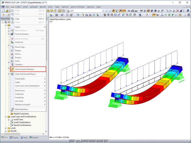
Generally, overlapping members in the model are not desired. To prevent RFEM from deleting an already defined member if another member is placed upon it, select "Allow Double Members" on the "Edit" menu.
.png?mw=640&hash=8fd04a597cecae2e434980ce79fc626815a5d98a)
The Aluminum Design Manual (ADM) 2020 was released in February 2020. The ADM 2020 gives guidance for both the allowable strength design (ASD) and load and resistance factor design (LRFD) for aluminum members to ensure reliability and safety for all aluminum structures. This latest standard was integrated in the RFEM/RSTAB add-on module RF-/ALUMINUM ADM. The text below will highlight the applicable updates relevant to the Dlubal programs.
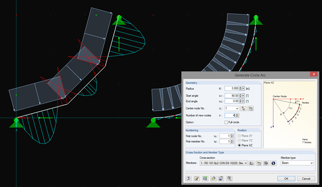
In addition to straight beams, it is sometimes necessary to calculate or design arched or circular beams in RSTAB. For this purpose, there is a special feature under "Tools" → "Generate Model – Members" → "Circle". You can easily use this tool to generate a full or pitch circle. The most important parameter here is the number of new nodes, which affects the accuracy of the results.

The ASCE 7-22 Standard [1], Sect. 12.9.1.6 specifies when P-delta effects should be considered when running a modal response spectrum analysis for seismic design. In the NBC 2020 [2], Sent. 4.1.8.3.8.c gives only a short requirement that sway effects due to the interaction of gravity loads with the deformed structure should be considered. Therefore, there may be situations where second-order effects, also known as P-delta, must be considered when carrying out a seismic analysis.

In RF‑/STEEL EC3, you can assign the same input data to several members or sets of members at the same time. The simultaneous assignment of the input data is possible for intermediate supports, effective lengths, nodal supports, member end hinges, and shear panel and rotational restraint.

For the stability verification of members using the equivalent member method, it is necessary to define effective or lateral-torsional buckling lengths in order to determine a critical load for stability failure. In this article an RFEM 6-specific function is presented, by which you can assign an eccentricity to the nodal supports and thus influence the determination of the critical bending moment considered in the stability analysis.
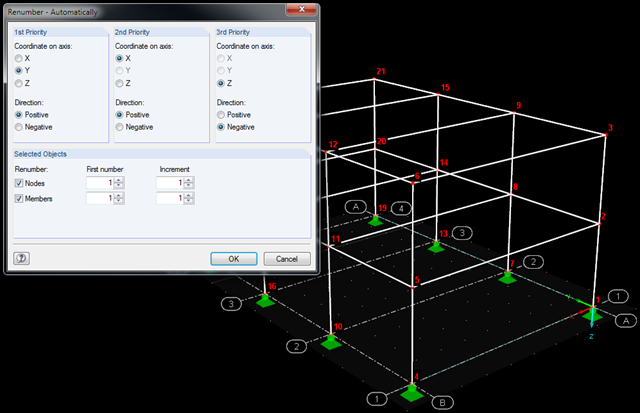
When modeling a structure, irregular numbering of objects may occur due to copying, dividing lines and members, and so on. Automatic renumbering allows you to restructure the numbering and thus to improve the clear arrangement. This function is applicable to nodes and members as well as for lines, surfaces, and solids in RFEM.
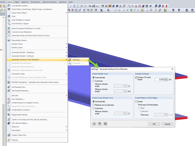
RFEM allows you to automatically generate surfaces from modeled members. This has the advantage that, for example, the surface thicknesses of a steel section are generated automatically.

When defining the effective slab width of T-beams, RFEM provides the predefined widths that are determined as 1/6 and 1/8 of the member length. A more detailed explanation on these two factors is given below.
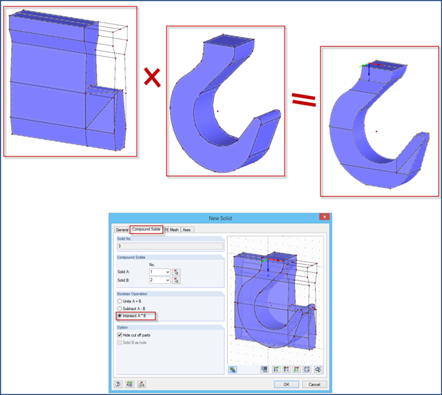
The "Intersect" option may facilitate the modeling of complex solids. This option is available in the shortcut menu after selecting two solids.
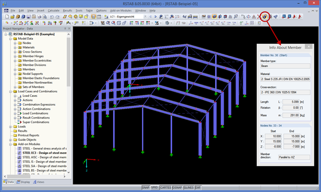
You may already be familiar with the "Center of Gravity and Info" function, which can be accessed using the shortcut menu of any element. If you want to display this information on several elements consecutively, you have to close the dialog box and open the shortcut menu of the next element over and over again.

In RFEM, you have the option to create and analyze cables using sheaves. For this, use the "Cable on Pulleys" member type. It is ideal for pulley systems, where the longitudinal forces are transferred via sheaves.
With the RF-STABILITY and RSBUCK add-on modules for RFEM and RSTAB, it is possible to perform eigenvalue analyses for member structures in order to determine the effective length factors. The effective length coefficients can then be used for the stability design.

The stiffening of timber structures is usually carried out by means of timber panels. For this purpose, structural components consisting of slabs (chipboard, OSB) are connected with members. Several articles will describe the basics of this construction method and the calculation in the RFEM program. This first article describes the basic determination of the stiffnesses as well as the calculation.

The calculation of timber panels is carried out on simplified member or surface structures. This article describes how to determine the required stiffness.

This article deals with the determination of the concrete reinforcement for a beam stressed by tension only according to EN 1992-1-1. The aim is to show the tensile load of a member-type element (without imposed deformations) and to define the concrete reinforcement in accordance with the standard's construction rules and provisions using the RFEM structural analysis software.
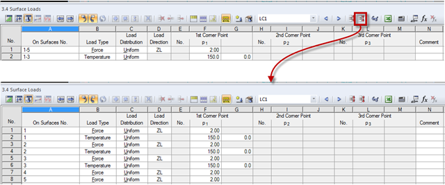
The load tables provide a simple option to control the applied loads. Dividing loads into individual lines is expedient. After dividing loads into the load table, the load data are displayed by a structural element (nodes, members, lines, surfaces, or solids). Thus, the load data analysis of each structural element is facilitated. The load case data can be compressed later.