21 Wyniki
Wyświetl wyniki:
Sortuj według:

Niniejszy artykuł dotyczy długotrwałego ugięcia konstrukcji betonowych zgodnie z ACI 318 i CSA A23.3.

Artykuł 4.1.8.7 kanadyjskich przepisów budowlanych (NBC) 2020 zawiera jasną procedurę dotyczącą metod analizy trzęsień ziemi. Metoda bardziej zaawansowana, a mianowicie metoda analizy dynamicznej opisana w rozdziale 4.1.8.12, powinna być stosowana dla wszystkich typów konstrukcji, z wyjątkiem tych, które spełniają kryteria podane w 4.1.8.7. W przypadku pozostałych konstrukcji, może być stosowana nieco prostsza metoda równoważnych sił statycznych (ESFP), opisana w rozdziale 4.1.8.11.

Analiza sejsmiczna w programie RFEM 6 jest możliwa przy użyciu rozszerzeń analizy modalnej i analizy spektrum odpowiedzi. Ogólna koncepcja analizy sejsmicznej w programie RFEM 6 opiera się na utworzeniu przypadku obciążenia do analizy modalnej lub analizy spektrum odpowiedzi. Grupy norm dla tych analiz są ustawiane w zakładce Normy II w oknie Dane podstawowe modelu.

W tym artykule wyjaśniono, jak działają obliczenia podczas wstępnej analizy sztywności w programie Połączenia stalowe.

Norma ASCE 7-22 [1], rozdz. 12.9.1.6 określa, kiedy efekty P-delta powinny być uwzględniane podczas przeprowadzania analizy modalnego spektrum odpowiedzi dla obliczeń sejsmicznych. W NBC 2020 [2], Wys. 4.1.8.3.8.c jedynie w niewielkim stopniu wymaga uwzględnienia przechyłów spowodowanych interakcją obciążeń grawitacyjnych z konstrukcją odkształconą. Z tego względu podczas przeprowadzania analizy sejsmicznej mogą wystąpić sytuacje, w których efekty drugiego rzędu, znane również jako P-delta, muszą zostać uwzględnione.

Dzięki rozszerzeniu Połączenia stalowe dla RFEM 6 można tworzyć i analizować połączenia stalowe przy użyciu wydzielonego modelu ES. Modelowanie połączeń można kontrolować poprzez proste i wygodne wprowadzanie elementów. Elementy stalowego połączenia można definiować ręcznie lub przy użyciu szablonów dostępnych w bibliotece. Pierwsza metoda została opisana w poprzednim artykule z Bazy wiedzy zatytułowanym „Nowe podejście do wymiarowania połączeń stalowych w programie RFEM 6”. W tym artykule skupimy się na tej drugiej metodzie; tzn. pokaże, jak definiować komponenty połączenia stalowego przy użyciu szablonów dostępnych w bibliotece programu.
Rozszerzenie Analiza etapów budowy (CSA) umożliwia wymiarowanie konstrukcji prętowych, powierzchniowych i bryłowych w programie RFEM 6 z uwzględnieniem określonych etapów budowy związanych z procesem konstrukcyjnym. Jest to o tyle istotne, że budynki nie powstają w całości od razu, lecz poprzez stopniowe łączenie poszczególnych części konstrukcyjnych. Poszczególne kroki, w których elementy konstrukcyjne oraz obciążenia są dodawane do budynku, nazywane są etapami budowy, podczas gdy sam proces budowy nazywa się procesem konstrukcyjnym.
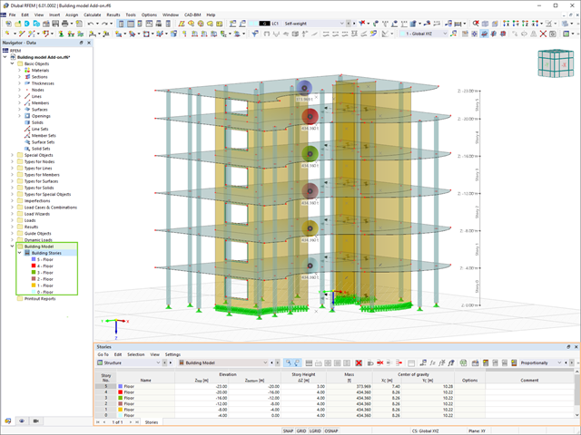
Model budynku jest jednym ze specjalnych rozszerzeń w programie RFEM 6. Jest to przydatne narzędzie do modelowania, za pomocą którego można łatwo tworzyć kondygnacje budynków i nimi manipulować. Model budynku można aktywować na początku procesu modelowania lub po jego zakończeniu.

W tym artykule przedstawiono model połączenia zakładkowego płatwi ZL na dachu jednospadowym, obliczony w rozszerzeniu Połączenia stalowe i porównany z tabelą nośności podaną przez producenta.

Z tego artykułu dowiesz się, jak zamodelować proste połączenie z blachą czołową w programie RFEM 6.

Jedną z innowacji w programie RFEM 6 jest nowy sposób projektowania połączeń stalowych. W przeciwieństwie do programu RFEM 5, w którym wymiarowanie połączeń stalowych opiera się na rozwiązaniu analitycznym, rozszerzenie Połączenia stalowe w programie RFEM 6 oferuje rozwiązanie dla połączeń stalowych w oparciu o analizę MES.

Zaletą modułu dodatkowego RFEM 6 Steel Joints jest możliwość analizy połączeń stalowych przy użyciu modelu MES, dla którego modelowanie przebiega w pełni automatycznie w tle. Elementy składowe złącza stalowego, które kontrolują modelowanie, można wprowadzić, definiując je ręcznie lub korzystając z dostępnych szablonów w bibliotece. Ta ostatnia metoda została opisana w poprzednim artykule z Bazy wiedzy zatytułowanym „Definiowanie komponentów połączenia stalowego przy użyciu biblioteki”. Definiowanie parametrów do wymiarowania połączeń stalowych jest tematem artykułu w bazie wiedzy „Projektowanie połączeń stalowych w RFEM 6”.

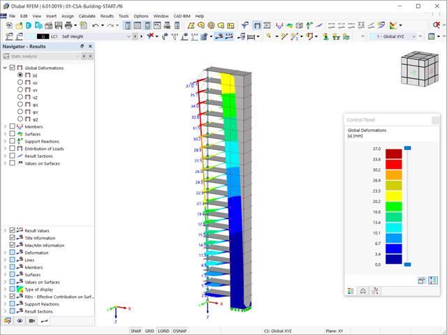
Ocena przemieszczenia kondygnacji w budynku jest kluczowa dla zapewnienia zadowalających parametrów konstrukcyjnych poprzez ograniczenie przemieszczenia kondygnacji. Nadmierne znoszenie może powodować niestateczność systemu i powodować uszkodzenia elementów niekonstrukcyjnych, takich jak ściany działowe. W tym artykule opisano procedurę wyznaczania przemieszczeń międzykondygnacyjnych zgodnie z ASCE 7-22 i rozszerzeniem Model budynku w programie RFEM 6.

Zrozumienie sztywności połączeń stalowych ma kluczowe znaczenie w projektowaniu konstrukcji. Często połączenia są traktowane jako połączenia całkowicie sztywne lub przegubowe, co może prowadzić do nieekonomicznych lub nawet ryzykownych warunków projektowych. Dowiedz się, w jaki sposób program RFEM firmy Dlubal i rozszerzenie Połączenia stalowe pomagają weryfikować sztywność połączeń i nośność na zginanie, zapewniając bezpieczniejsze i bardziej ekonomiczne warunki projektowe.

Obliczenia konstrukcji złożonych za pomocą oprogramowania do analizy elementów skończonych są zazwyczaj przeprowadzane na całym modelu. Jednak wznoszenie tego typu konstrukcji jest procesem wieloetapowym, w którym ostateczny stan konstrukcji uzyskuje się poprzez połączenie poszczególnych elementów konstrukcyjnych. Aby uniknąć błędów w obliczeniach ogólnych modeli, należy wziąć pod uwagę wpływ procesu konstrukcyjnego. W programie RFEM 6 jest to możliwe za pomocą rozszerzenia Analiza etapów budowy (CSA).

Podczas obliczania regularnych konstrukcji wprowadzanie danych często nie jest skomplikowane, ale czasochłonne. Oszczędzaj cenny czas dzięki automatycznemu wprowadzaniu danych. W niniejszym przypadku należy uwzględnić kondygnacje domu jako poszczególne etapy budowy. Dane są wprowadzane przy pomocy programu w języku C#, aby użytkownik nie musiał ręcznie wprowadzać elementów poszczególnych pięter.

Zarówno analiza drgań własnych, jak i analiza spektrum odpowiedzi przeprowadzane są na układzie liniowym. Jeżeli w modelu występują nieliniowości, podlega on linearyzacji, dzięki czemu elementy nieliniowe nie są brane pod uwagę w dalszej analizie. Mogą to być na przykład pręty rozciągane, podpory nieliniowe lub przeguby nieliniowe. W tym artykule pokazano, w jaki sposób można nimi zarządzać w analizie dynamicznej.

W tym artykule pokażemy, jak zdefiniować żebra podłużne na blasze pręta za pomocą komponentu „Żebro” w rozszerzeniu Połączenia stalowe.

W programie RFEM 6 połączenia stalowe definiuje się jako układ elementów. W nowym rozszerzeniu Połączenia stalowe dostępne są podstawowe komponenty do uniwersalnego zastosowania (blachy, spoiny, płaszczyzny pomocnicze). Metody definiowania połączeń opisano w dwóch poprzednich artykułach w Bazie informacji: „Nowe podejście do wymiarowania połączeń stalowych w programie RFEM 6” oraz „Definiowanie elementów połączenia stalowego przy użyciu biblioteki” .
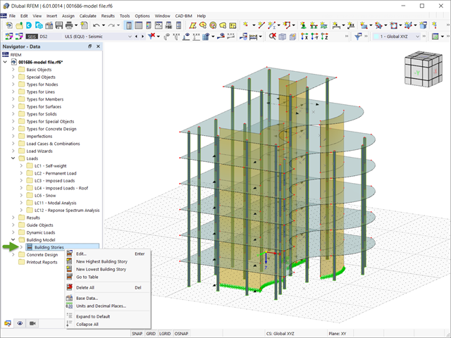
W programie RFEM 6 analizę sejsmiczną można przeprowadzić za pomocą modułów dodatkowych Analiza modalna i Analiza spektrum odpowiedzi. Zaraz po zakończeniu analizy spektralnej za pomocą rozszerzenia Model budynku można wyświetlić oddziaływania kondygnacji, przemieszczenia kondygnacji i siły w ścianach usztywniających.

Aby ocenić, czy w obliczeniach dynamicznych konieczne jest również uwzględnienie analizy drugiego rzędu, w normie EN 1998‑1, sekcje 2.2.2 i 4.4.2.2 zawarto współczynnik wrażliwości międzykondygnacyjnego znoszenia θ. Można ją obliczyć i przeanalizować za pomocą programów RFEM 6 i RSTAB 9.