46 Wyniki
Wyświetl wyniki:
Sortuj według:

Z tego artykułu dowiesz się, jak modelować usztywnione połączenia rurowe w rozszerzeniu Połączenia stalowe.

Niniejszy artykuł dotyczy długotrwałego ugięcia konstrukcji betonowych zgodnie z ACI 318 i CSA A23.3.

W tym artykule pokażemy, jak zdefiniować żebra podłużne na blasze pręta za pomocą komponentu „Żebro” w rozszerzeniu Połączenia stalowe.

Dzięki rozszerzeniu Projektowanie konstrukcji stalowych możliwe jest projektowanie konstrukcji stalowych zgodnie z normą AISC 360-22. W poniższym artykule porównano wyniki obliczeń zwichrzenia zgodnie z rozdziałem F z analizą wartości własnych.

Z tego artykułu dowiesz się, jak zamodelować proste połączenie z blachą czołową w programie RFEM 6.

Blachownica to ekonomiczny wybór w przypadku konstrukcji o dużych rozpiętościach. I-section steel plate girder typically has a deep web to maximize its shear capacity and flange separation, yet thin web to minimize the self-weight. Due to its large height-to-thickness (h/tw) ratio, transverse stiffeners may be required to stiffen the slender web.

Wyboczenie giętno-skrętne (LTB) jest zjawiskiem, które występuje, gdy belka lub element konstrukcyjny są zginane, a pas ściskany nie jest wystarczająco podparty bocznie. Prowadzi to do kombinacji przemieszczenia bocznego i skręcenia. Jest to decydujący czynnik przy wymiarowaniu elementów konstrukcyjnych, zwłaszcza smukłych belek i dźwigarów.

Zrozumienie sztywności połączeń stalowych ma kluczowe znaczenie w projektowaniu konstrukcji. Często połączenia są traktowane jako połączenia całkowicie sztywne lub przegubowe, co może prowadzić do nieekonomicznych lub nawet ryzykownych warunków projektowych. Dowiedz się, w jaki sposób program RFEM firmy Dlubal i rozszerzenie Połączenia stalowe pomagają weryfikować sztywność połączeń i nośność na zginanie, zapewniając bezpieczniejsze i bardziej ekonomiczne warunki projektowe.

Obliczanie ramy momentowej zgodnie z AISC 341-16 jest teraz możliwe w rozszerzeniu Projektowanie konstrukcji stalowych dla programu RFEM 6. Wynik obliczeń sejsmicznych jest podzielony na dwie sekcje: wymagania dotyczące prętów i połączeń. W tym artykule omówiono wymaganą wytrzymałość połączenia. Przedstawiono przykładowe porównanie wyników pomiędzy RFEM a AISC Seismic Design Manual.

W rozszerzeniu Projektowanie konstrukcji stalowych dla programu RFEM 6 dostępne są trzy typy ram sprężystych (zwykłe, pośrednie i specjalne). Wyniki obliczeń sejsmicznych zgodnie z AISC 341-22 są podzielone na dwie sekcje: wymagania dotyczące prętów i połączeń.

W rozszerzeniu Projektowanie konstrukcji stalowych dla programu RFEM 6 dostępne są trzy typy ram sprężystych (zwykłe, pośrednie i specjalne). Wyniki obliczeń sejsmicznych zgodnie z AISC 341-16 są podzielone na dwie sekcje: wymagania dotyczące prętów i połączeń.

W tym artykule opisano na przykładzie płyty z betonu włóknistego, które wpływają na zastosowanie różnych metod całkowania i różnej liczby punktów całkowania na wynik obliczeń.
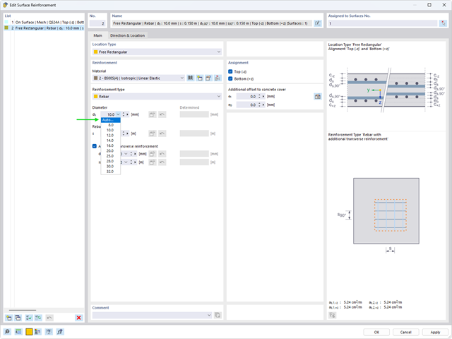
Automatyczny proces wymiarowania zbrojenia określa zbrojenie powierzchniowe, które zapewnia wymaganą ilość zbrojenia wynikającego z obliczeń.
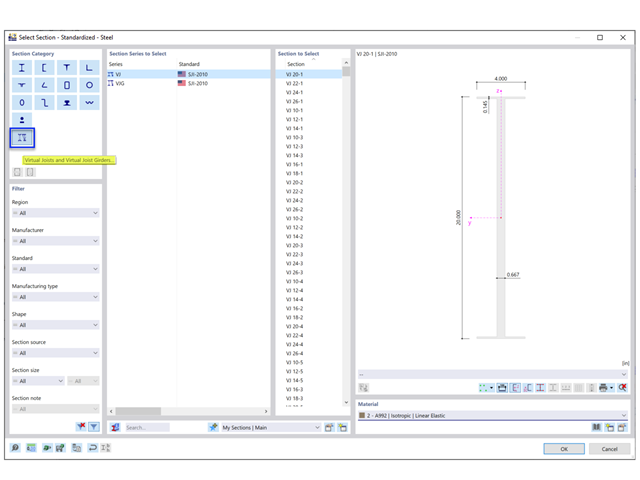
Steel Joist Institute (SJI) wcześniej opracował tabele wirtualnych belek nośnych w celu oszacowania właściwości przekroju dla belek stalowych z otwartym środnikiem. Te przekroje belek wirtualnych są scharakteryzowane jako równoważne belki o szerokich półkach, które są bardzo zbliżone do pola powierzchni pasa, efektywnego momentu bezwładności i ciężaru. Wirtualne belki nośne są również dostępne w bazie danych przekrojów w programach RFEM i RSTAB.

Rozszerzenie Projektowanie konstrukcji stalowych w RFEM 6 oferuje teraz możliwość przeprowadzania obliczeń sejsmicznych zgodnie z AISC 341-16 i AISC 341-22. Obecnie dostępnych jest pięć typów systemów sejsmicznych (SFRS).

W tym artykule wyjaśniono, jak działają obliczenia podczas wstępnej analizy sztywności w programie Połączenia stalowe.
Blachownica to ekonomiczny wybór w przypadku konstrukcji o dużych rozpiętościach. I-section steel plate girder typically has a deep web to maximize its shear capacity and flange separation, yet thin web to minimize the self-weight. Due to its large height-to-thickness (h/tw) ratio, transverse stiffeners may be required to stiffen the slender web.
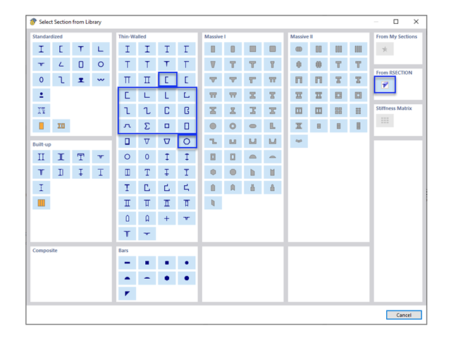
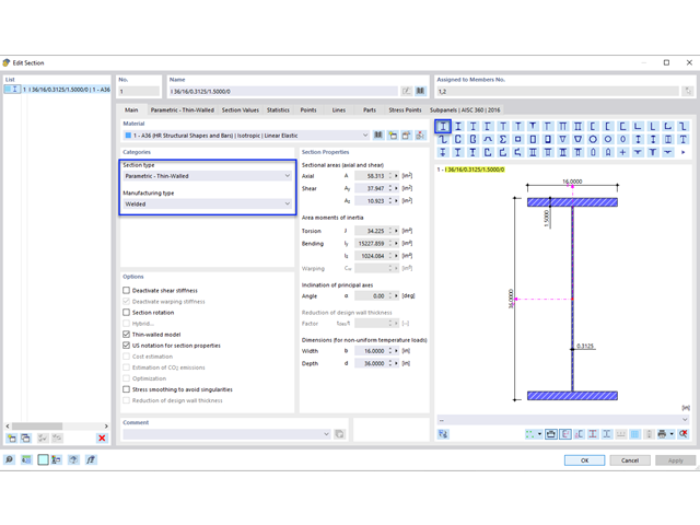
W obliczeniach konstrukcji stalowych formowanych na zimno często wymagane są niestandardowe przekroje. In RFEM 6, the custom section can be created using one of the “Thin-Walled” sections available in the library. For other sections that do not meet any of the 14 available cold-formed shapes, the sections can be created and imported from the standalone program, RSECTION. For general information on AISI steel design in RFEM 6, refer to the Knowledge Base article provided at the end of the page.

Jeżeli, na przykład, do określenia sił wewnętrznych ma zostać zastosowany model czysto powierzchniowy, ale wymiarowanie komponentu nadal odbywa się na modelu prętowym, można skorzystać z belki wynikowej.

Obliczenia zwykłej ramy stężonej koncentrycznie (OCBF) oraz SCBF (specjalnej konstrukcji szkieletowej stężonej koncentrycznie) można przeprowadzić w rozszerzeniu Projektowanie konstrukcji stalowych dla programu RFEM 6. Wyniki obliczeń sejsmicznych zgodnie z AISC 341-16 i 341-22 są podzielone na dwie sekcje: Wymagania dotyczące prętów i połączeń.
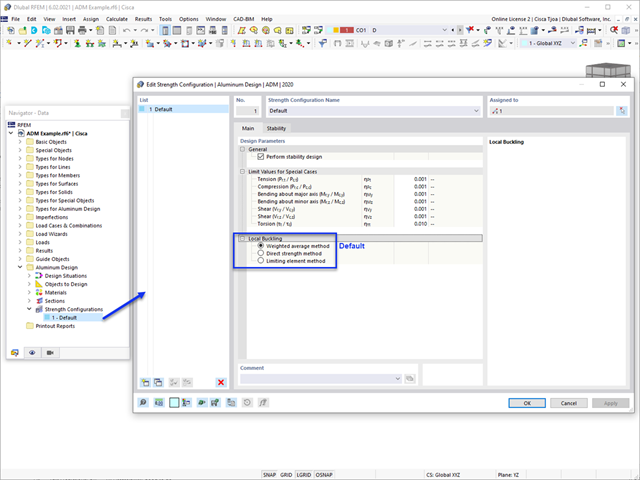
W tym artykule omówiono dostępne opcje określania nominalnej wytrzymałości na zginanie Mnlb dla stanu granicznego wyboczenia lokalnego, podczas projektowania zgodnie z Aluminium Design Manual (Podręcznik projektowania konstrukcji aluminiowych 2020).

Wymiarowanie prętów stalowych formowanych na zimno zgodnie z AISI S100-16 jest teraz dostępne w programie RFEM 6. Design can be accessed by selecting “AISC 360” as the standard in the Steel Design add-on. “AISI S100” is then automatically selected for the cold-formed design (Image 01).

Obliczenia ze względu na zmęczenie zgodnie z EN 1992-1-1 należy przeprowadzać w przypadku elementów konstrukcyjnych, które są poddane działaniu dużych zakresów naprężeń i/lub wielu zmianom obciążenia. W takim przypadku obliczenia dla betonu i zbrojenia są przeprowadzane osobno. Dostępne są dwie alternatywne metody obliczeniowe.
![Rozpiętości na podstawie Rysunku 5.2 z [1]](/pl/webimage/039540/3493372/01_Abmessungen_EN.png?mw=640&hash=a3c436931baff3514db261b2d11bfa39abae9170)
Aby poprawnie zwymiarować dźwigar lub belkę teową w programie RFEM 6 i w module dodatkowym 'Wymiarowanie betonu', ważne jest określenie 'szerokości pasów' prętów żebrowych. W tym artykule omówiono opcje wprowadzania danych dla belki dwuprzęsłowej oraz obliczanie wymiarów pasów zgodnie z EN 1992-1-1.

Dzięki rozszerzeniu Połączenia stalowe dla RFEM 6 można tworzyć i analizować połączenia stalowe przy użyciu wydzielonego modelu ES. Modelowanie połączeń można kontrolować poprzez proste i wygodne wprowadzanie elementów. Elementy stalowego połączenia można definiować ręcznie lub przy użyciu szablonów dostępnych w bibliotece. Pierwsza metoda została opisana w poprzednim artykule z Bazy wiedzy zatytułowanym „Nowe podejście do wymiarowania połączeń stalowych w programie RFEM 6”. W tym artykule skupimy się na tej drugiej metodzie; tzn. pokaże, jak definiować komponenty połączenia stalowego przy użyciu szablonów dostępnych w bibliotece programu.

Zaletą modułu dodatkowego RFEM 6 Steel Joints jest możliwość analizy połączeń stalowych przy użyciu modelu MES, dla którego modelowanie przebiega w pełni automatycznie w tle. Elementy składowe złącza stalowego, które kontrolują modelowanie, można wprowadzić, definiując je ręcznie lub korzystając z dostępnych szablonów w bibliotece. Ta ostatnia metoda została opisana w poprzednim artykule z Bazy wiedzy zatytułowanym „Definiowanie komponentów połączenia stalowego przy użyciu biblioteki”. Definiowanie parametrów do wymiarowania połączeń stalowych jest tematem artykułu w bazie wiedzy „Projektowanie połączeń stalowych w RFEM 6”.
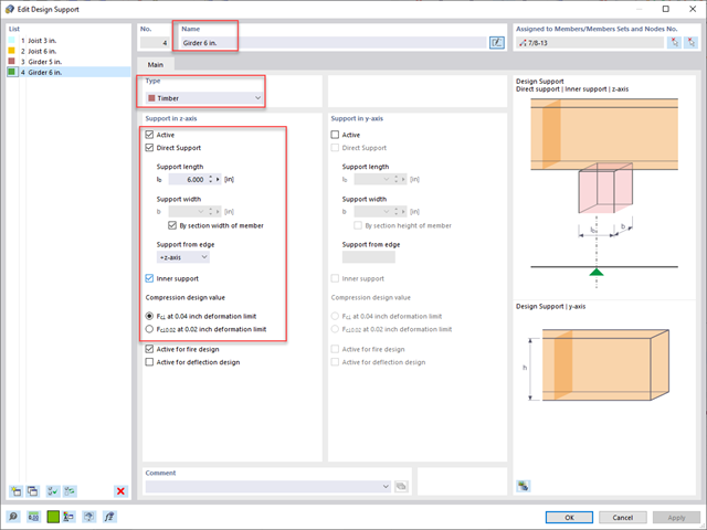
Standardowym rozwiązaniem w konstrukcji prętów drewnianych jest możliwość łączenia mniejszych prętów poprzez podparcie na większym dźwigarze. Dodatkowo warunki na końcach pręta mogą uwzględniać podobną sytuację, w której belka jest oparta na podporze. W obu przypadkach belka musi być zaprojektowana tak, aby uwzględniała nośność w poprzek włókien zgodnie z NDS 2018 s. 3.10.2 i CSA O86:19 punkty 6.5.6 i 7.5.9. W ogólnych programach do projektowania statyczno-wytrzymałościowego zazwyczaj nie jest możliwe przeprowadzenie pełnej kontroli obliczeń, ponieważ powierzchnia docisku jest nieznana. Jednak w programie RFEM 6 nowej generacji i rozszerzeniu Projektowanie konstrukcji drewnianych dodana funkcja "podpór obliczeniowych" umożliwia teraz użytkownikom uwzględnienie docisku NDS i CSA prostopadle do warunków obliczeniowych.
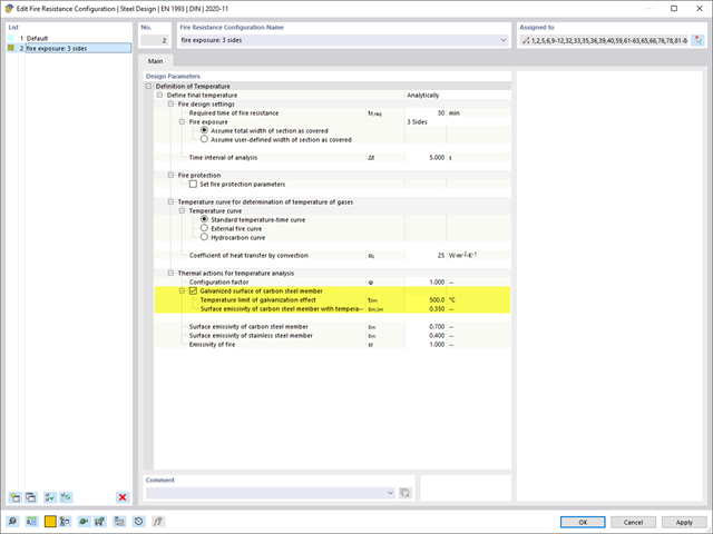
Rozszerzenie Projektowanie konstrukcji stalowych umożliwia wymiarowanie stalowych elementów konstrukcyjnych na wypadek pożaru, z zastosowaniem prostych metod obliczeniowych, zgodnie z Eurokodem 3. Temperatura elementu w chwili wykrycia może być określana automatycznie na podstawie krzywych temperatura-czas określonych w normie. Oprócz uwzględnienia okładzin przeciwpożarowych można również wziąć pod uwagę korzystne właściwości cynkowania ogniowego.
,_Table_22.5.5.1_ACI_318-19.png?mw=640&hash=7e50d54e01238943fe1c691c0aa197d9b2fa8511)
W najnowszej normie ACI 318-19 długoterminowa zależność w określaniu nośności betonu na ścinanieVc zostaje przedefiniowana. Dzięki nowej metodzie wysokość pręta, stopień zbrojenia podłużnego i naprężenie normalne wpływają teraz na wytrzymałość na ścinanie Vc. W poniższym artykule opisano zaktualizowane podejście do obliczeń dla ścinania, a zastosowanie przedstawiono na przykładzie.

W tym artykule przedstawiono model połączenia zakładkowego płatwi ZL na dachu jednospadowym, obliczony w rozszerzeniu Połączenia stalowe i porównany z tabelą nośności podaną przez producenta.