238 Wyniki
Wyświetl wyniki:
Sortuj według:

Niniejszy artykuł dotyczy długotrwałego ugięcia konstrukcji betonowych zgodnie z ACI 318 i CSA A23.3.

Analiza wyboczenia giętnego jest połączeniem analizy stateczności i stanu granicznego nośności, stosowana w konstrukcjach stalowych od setek lat. Punktem wyjścia do rozważenia kwestii stateczności jest krytyczne obciążenie wyboczeniowe, ale dotychczas nie przeprowadzono obliczeń bez uwzględnienia imperfekcji. Jak dokładnie określane są te imperfekcje?

Podczas obliczania siły tnącej w programie Wymiarowanie betonu zbrojonego, działającą siłę tnącą Vz można zredukować zgodnie z EN 1992-1-1. Poniższy artykuł opisuje redukcję siły tnącej od obciążeń skupionych w pobliżu podpory oraz wymiarowanie sił tnących w odległości d od krawędzi podpory w przypadku obciążenia równomiernie rozłożonego.

Podczas obliczania regularnych konstrukcji wprowadzanie danych często nie jest skomplikowane, ale czasochłonne. Oszczędzaj cenny czas dzięki automatycznemu wprowadzaniu danych. W niniejszym przypadku należy uwzględnić kondygnacje domu jako poszczególne etapy budowy. Dane są wprowadzane przy pomocy programu w języku C#, aby użytkownik nie musiał ręcznie wprowadzać elementów poszczególnych pięter.

Z tego artykułu dowiesz się, jak zamodelować proste połączenie z blachą czołową w programie RFEM 6.

Dzięki rozszerzeniu Projektowanie konstrukcji stalowych możliwe jest projektowanie konstrukcji stalowych zgodnie z normą AISC 360-22. W poniższym artykule porównano wyniki obliczeń zwichrzenia zgodnie z rozdziałem F z analizą wartości własnych.
![Podstawowe kształty konstrukcji membranowych [1]](/pl/webimage/009595/2419506/01-png.png?mw=640&hash=8a9ac87bf3acfb73e6cad970f55eb968a841595c)
Niniejszy artykuł skupia się na specyficznych aspektach projektowania konstrukcji membranowych, które mają specyficzne wymagania, takich jak znajdowanie kształtu (form-finding) i generowanie szablonów cięcia. Integralną częścią projektowania tych konstrukcji jest proces wyszukiwania odpowiednich wstępnie sprężonych kształtów i generowania szablonów cięcia. Tekst krótko opisuje dwa podstawowe procesy w projektowaniu konstrukcji membranowych. Celem jest zilustrowanie ich fizycznego charakteru i zademonstrowanie poszczególnych stwierdzeń za pomocą towarzyszących im przykładów.
W inżynierii konstrukcyjnej przewidywanie wpływu turbulentnego przepływu wiatru na konstrukcje ma kluczowe znaczenie dla bezpieczeństwa i wydajności. Modelowanie turbulencji w Computational Fluid Dynamics (CFD) pomaga w symulacji tych interakcji. Inżynierowie muszą wybrać praktyczny model turbulencji, równoważąc wydajność, dokładność i możliwości zastosowania. Typowe modele to uśredniony Navier-Stokes (RANS), niestabilny uśredniony Navier-Stokes (URANS) oraz Delayed Detached Eddy Simulation (DDES). Program RANS jest niezawodnym i ekonomicznym rozwiązaniem w przypadku stałych przepływów, URANS rejestruje zależne od czasu zjawiska dla średnich niestateczności, a DDES, hybryda RANS i symulacji dużych wirów (LES), rozwiązuje złożone struktury turbulentne. Zrozumienie mocnych stron i ograniczeń każdego modelu pomoże inżynierom wybrać najlepsze podejście do swoich potrzeb.

Norma ASCE 7-22 [1], rozdz. 12.9.1.6 określa, kiedy efekty P-delta powinny być uwzględniane podczas przeprowadzania analizy modalnego spektrum odpowiedzi dla obliczeń sejsmicznych. W NBC 2020 [2], Wys. 4.1.8.3.8.c jedynie w niewielkim stopniu wymaga uwzględnienia przechyłów spowodowanych interakcją obciążeń grawitacyjnych z konstrukcją odkształconą. Z tego względu podczas przeprowadzania analizy sejsmicznej mogą wystąpić sytuacje, w których efekty drugiego rzędu, znane również jako P-delta, muszą zostać uwzględnione.

Artykuł 4.1.8.7 kanadyjskich przepisów budowlanych (NBC) 2020 zawiera jasną procedurę dotyczącą metod analizy trzęsień ziemi. Metoda bardziej zaawansowana, a mianowicie metoda analizy dynamicznej opisana w rozdziale 4.1.8.12, powinna być stosowana dla wszystkich typów konstrukcji, z wyjątkiem tych, które spełniają kryteria podane w 4.1.8.7. W przypadku pozostałych konstrukcji, może być stosowana nieco prostsza metoda równoważnych sił statycznych (ESFP), opisana w rozdziale 4.1.8.11.
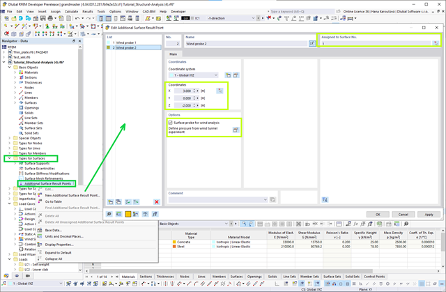
Jeśli dostępne są wyniki parcia powierzchniowego na budynek wywołane wiatrem, można je zastosować w modelu konstrukcyjnym w programie RFEM 6, przetworzonym przez RWIND 2 i wykorzystać jako obciążenia wiatrem do analizy statycznej w RFEM 6.
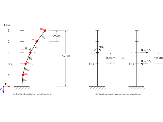
Zgodnie z normami EN 1998-1 sekcje 2.2.2 i 4.4.2.2 do obliczeń stanu granicznego nośności należy przeprowadzić obliczenia z uwzględnieniem teorii drugiego rzędu (efekt P-Δ). Efekt ten nie musi być uwzględniany tylko w przypadku, gdy współczynnik wrażliwości międzykondygnacyjnej jest mniejszy niż 0,1.
Stworzenie przykładu walidacyjnego dla obliczeniowej mechaniki płynów (CFD) jest kluczowym krokiem w zapewnieniu dokładności i wiarygodności wyników symulacji. This process involves comparing the outcomes of CFD simulations with experimental or analytical data from real-world scenarios. The objective is to establish that the CFD model can faithfully replicate the physical phenomena it is intended to simulate.

W tym artykule opisano na przykładzie płyty z betonu włóknistego, które wpływają na zastosowanie różnych metod całkowania i różnej liczby punktów całkowania na wynik obliczeń.
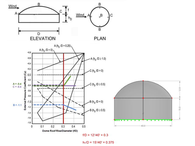
Jeśli chodzi o obciążenia wiatrem konstrukcje budowlane zgodnie z ASCE 7, można znaleźć wiele źródeł, które mogą uzupełnić normy projektowe i pomóc inżynierom w zastosowaniu obciążeń poprzecznych. Jednak inżynierom może być trudniej znaleźć podobne zasoby dla obciążeń wiatrem na konstrukcjach innych niż budynki. W tym artykule omówiono etapy obliczania i przykładania obciążeń wiatrem zgodnie z ASCE 7-22 na okrągłym zbiorniku żelbetowym z dachem w kształcie kopuły.
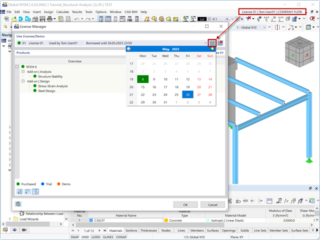
Wszystko jest online. Jest to również licencje Dlubal dla RFEM 6, RSTAB 9 i RSECTION. Ten artykuł zawiera informacje na temat stosowania licencji online i zarządzania nimi, rezerwowania licencji, sprawdzania ważności licencji i przenoszenia uprawnień między licencjami.
![Rozpiętości na podstawie Rysunku 5.2 z [1]](/pl/webimage/039540/3493372/01_Abmessungen_EN.png?mw=640&hash=a3c436931baff3514db261b2d11bfa39abae9170)
Aby poprawnie zwymiarować dźwigar lub belkę teową w programie RFEM 6 i w module dodatkowym 'Wymiarowanie betonu', ważne jest określenie 'szerokości pasów' prętów żebrowych. W tym artykule omówiono opcje wprowadzania danych dla belki dwuprzęsłowej oraz obliczanie wymiarów pasów zgodnie z EN 1992-1-1.
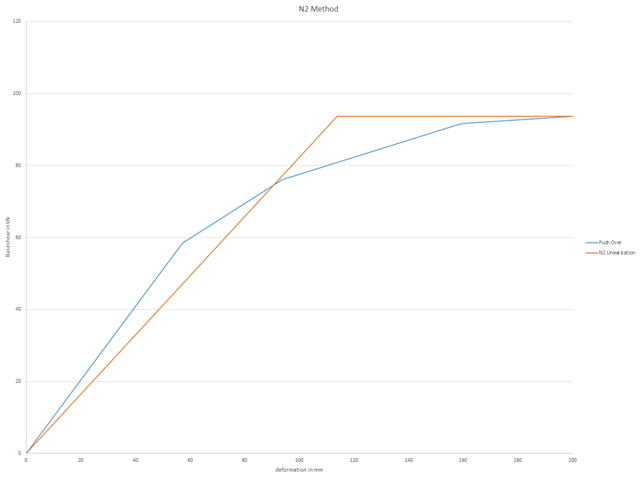
Aby można było przeprowadzić obliczenia push-over, należy zdefiniowaną krzywą nośności przekształcić do postaci uproszczonej. Tak zwana metoda N2 jest opisana w Eurokodzie EN 1998. Ten artykuł powinien pomóc w wyjaśnieniu, co oznacza bilinearyzacja zgodnie z metodą N2.

Zarówno analiza drgań własnych, jak i analiza spektrum odpowiedzi przeprowadzane są na układzie liniowym. Jeżeli w modelu występują nieliniowości, podlega on linearyzacji, dzięki czemu elementy nieliniowe nie są brane pod uwagę w dalszej analizie. Mogą to być na przykład pręty rozciągane, podpory nieliniowe lub przeguby nieliniowe. W tym artykule pokazano, w jaki sposób można nimi zarządzać w analizie dynamicznej.
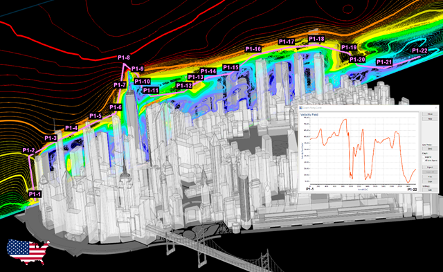
Zgodność z przepisami budowlanymi, takimi jak Eurokod, jest niezbędna dla zapewnienia bezpieczeństwa, integralności konstrukcji i trwałości budynków i konstrukcji. Obliczeniowa mechanika płynów (CFD) odgrywa istotną rolę w tym procesie, symulując zachowanie płynów, optymalizując projekty i pomagając architektom i inżynierom w spełnieniu wymagań Eurokodu związanych z analizą obciążenia wiatrem, wentylacją naturalną, bezpieczeństwem pożarowym i efektywnością energetyczną. Integrując CFD z procesem projektowania, profesjonaliści mogą tworzyć bezpieczniejsze, wydajniejsze i zgodne z przepisami budynki, które spełniają najwyższe standardy konstrukcyjne i projektowe w Europie.
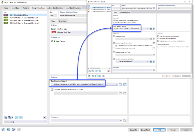
Analiza spektrum odpowiedzi jest jedną z najczęściej stosowanych metod obliczeniowych w przypadku obciążenia trzęsieniem ziemi. Metoda ta ma wiele zalet, a najważniejsza z nich to możliwość znacznego uproszczenia obliczeń. Skomplikowany charakter obciążenia jakim jest trzęsienie ziemi jest upraszczany do postaci, która umożliwia przeprowadzenie analizy o rozsądnym stopniu pracochłonności. Wadą metody jest natomiast to, że w wyniku tego uproszczenia traci się część informacji o obciążeniu. Sposobem na zniwelowanie tego ograniczenia może być zastosowanie równoważnej kombinacji liniowej podczas łączenia odpowiedzi modalnych. W poniższym artykule wyjaśniono to bardziej szczegółowo na konkretnym przykładzie.
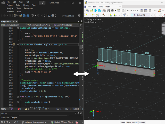
Nasza usługa sieciowa oferuje użytkownikom możliwość komunikacji z programami RFEM 6 i RSTAB 9 za pomocą różnych języków programowania. Funkcje wysokiego poziomu (HLF) firmy Dlubal umożliwiają rozszerzenie i uproszczenie funkcjonalności WebService. Zgodnie z RFEM 6 i RSTAB 9, korzystanie z naszego webservice sprawia, że praca inżyniera jest łatwiejsza i szybsza. Wypróbuj teraz! Ten samouczek pokazuje, jak korzystać z biblioteki C #na prostym przykładzie.
Jeżeli na górnej półce znajduje się płyta betonowa, działa ona jak podpora boczna (konstrukcja zespolona) i zapobiega problemom ze statecznością przy wyboczeniu skrętnym. Jeżeli moment zginający jest ujemny, dolna półka jest obciążona, a górna rozciągana. Jeżeli podparcie boczne nie jest wystarczające ze względu na sztywność środnika, kąt pomiędzy dolną półką a linią nacięcia środnika jest zmienny, przez co istnieje możliwość wystąpienia niestateczności wymiarowej dolnej półki.
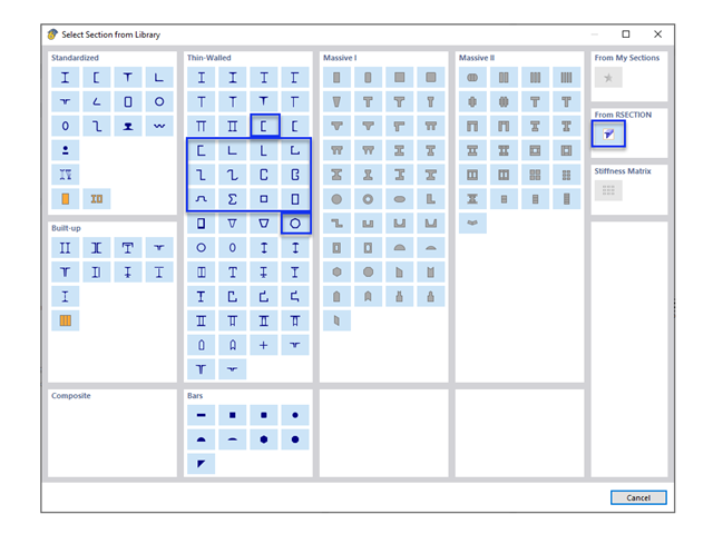
W obliczeniach konstrukcji stalowych formowanych na zimno często wymagane są niestandardowe przekroje. In RFEM 6, the custom section can be created using one of the “Thin-Walled” sections available in the library. For other sections that do not meet any of the 14 available cold-formed shapes, the sections can be created and imported from the standalone program, RSECTION. For general information on AISI steel design in RFEM 6, refer to the Knowledge Base article provided at the end of the page.
Połączenia stalowe w programie RFEM 6 można tworzyć poprzez wprowadzenie wstępnie zdefiniowanych komponentów w rozszerzeniu Połączenia stalowe. Lista tych elementów jest stale rozszerzana, aby ułatwić modelowanie połączeń stalowych. W tym artykule przedstawiamy blachę łączącą, która została niedawno dodana do biblioteki rozszerzenia.
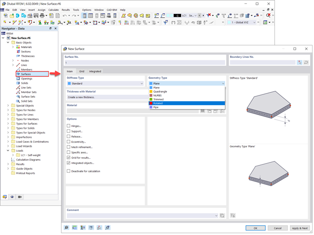
Powierzchnie w modelach budynków mogą mieć różne rozmiary i kształty. W programie RFEM 6 można uwzględnić wszystkie powierzchnie, ponieważ program umożliwia definiowanie różnych materiałów i grubości, a także powierzchni o różnej sztywności i typie geometrii. W tym artykule skupiono się na czterech z następujących typów powierzchni: obrócony, przycięty, bez grubości i przeniesienia obciążenia.
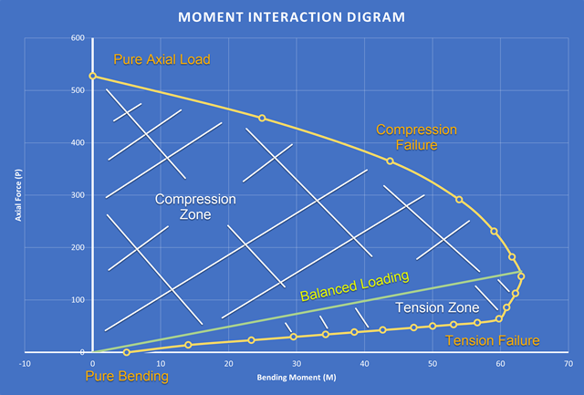
Nowością w programie RFEM 6 podczas wymiarowania słupów betonowych jest możliwość generowania wykresu interakcji momentów zgodnie z ACI 318-19 [1]. Podczas wymiarowania prętów żelbetowych istotnym narzędziem jest wykres interakcji momentów. Wykres interakcji momentów przedstawia zależność między momentem zginającym a siłą osiową w dowolnym punkcie zbrojenia. Cenne informacje, takie jak wytrzymałość i zachowanie betonu w różnych warunkach obciążenia, wyświetlane są wizualnie.
Metoda CSA S16:19 Skutki stateczności w analizie sprężystej w Załączniku O.2 stanowi alternatywę dla metody Uproszczonej analizy stateczności z punktu 8.4.3. W tym artykule zostaną opisane wymagania załącznika O.2 i zastosowania w RFEM 6.
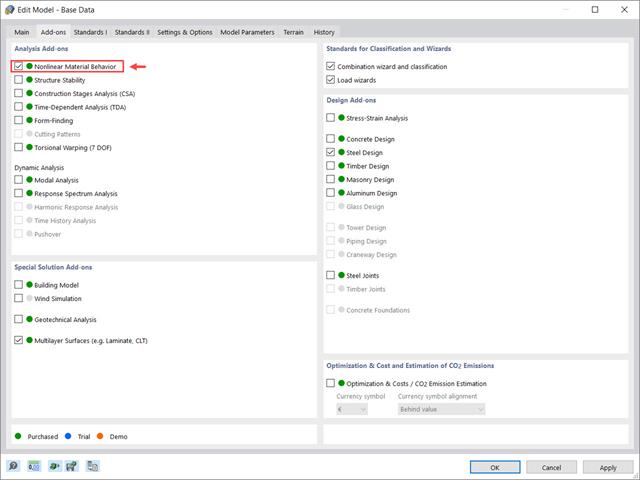
Rozszerzenie Nieliniowe zachowanie materiału umożliwia uwzględnienie nieliniowości materiałowych w programie RFEM 6. Ten artykuł zawiera przegląd dostępnych nieliniowych modeli materiałowych, które są dostępne po aktywowaniu tego rozszerzenia w danych bazowych modelu.
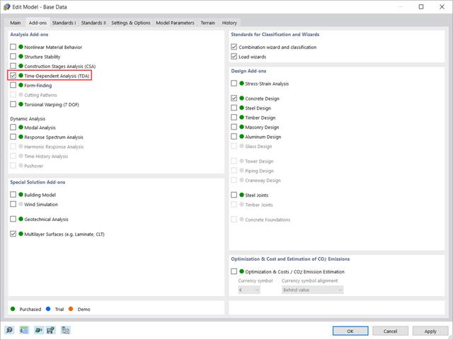
W tym artykule pokazano, w jaki sposób rozszerzenie „Analiza zależna od czasu” jest zintegrowane w programach RFEM 6 i RSTAB 9. Opisuje sposób definiowania danych wejściowych, takich jak charakterystyka materiału zależna od czasu, sposób określania typu analizy i czasy obciążenia.