Lunar Dome, USA
Customer Project
-
01
Apollo 11 Roadshow Tent at Night (© Matthew Churchill Productions Ltd.)
-
01
Daytime View (© Matthew Churchill Productions Ltd.)
-
01
Auditorium During Show (© Jim Cox Photography)
-
01
ETFE Façade Foyer (© Matthew Churchill Productions Ltd.)
-
01
Apollo 11 Roadshow Tent at Night (© Matthew Churchill Productions Ltd.)
-
01
Auditorium During Show (© Jim Cox Photography)
-
01
RFEM 3D Projection Dome Model (© formTL)
-
01
RFEM 3D Main Structure Model in RFEM (© formTL)
-
01
3D Model of Projection Dome in RFEM (© formTL)
-
01
3D Model of Main Supporting Structure in RFEM (© formTL)
-
02
Model of Main Supporting Structure with Deformation Animation in RFEM (© formTL)
-
02
Daytime View (© Matthew Churchill Productions Ltd.)
-
02
Auditorium During Show (© Jim Cox Photography)
-
02
ETFE Façade Foyer (© Matthew Churchill Productions Ltd.)
-
02
Apollo 11 Roadshow Tent at Night (© Matthew Churchill Productions Ltd.)
-
02
Auditorium During Show (© Jim Cox Photography)
-
02
RFEM 3D Projection Dome Model (© formTL)
-
02
RFEM 3D Main Structure Model in RFEM (© formTL)
-
02
3D Model of Projection Dome in RFEM (© formTL)
-
02
3D Model of Main Supporting Structure in RFEM (© formTL)
-
03
RFEM 3D Main Structure Model in RFEM (© formTL)
-
03
Daytime View (© Matthew Churchill Productions Ltd.)
-
03
Auditorium During Show (© Jim Cox Photography)
-
03
ETFE Façade Foyer (© Matthew Churchill Productions Ltd.)
-
03
Apollo 11 Roadshow Tent at Night (© Matthew Churchill Productions Ltd.)
-
03
RFEM 3D Projection Dome Model (© formTL)
-
03
RFEM 3D Main Structure Model in RFEM (© formTL)
-
03
3D Model of Projection Dome in RFEM (© formTL)
-
03
3D Model of Main Supporting Structure in RFEM (© formTL)
-
04
RFEM 3D Projection Dome Model (© formTL)
-
04
Daytime View (© Matthew Churchill Productions Ltd.)
-
04
Auditorium During Show (© Jim Cox Photography)
-
04
ETFE Façade Foyer (© Matthew Churchill Productions Ltd.)
-
04
Apollo 11 Roadshow Tent at Night (© Matthew Churchill Productions Ltd.)
-
04
Auditorium During Show (© Jim Cox Photography)
-
04
RFEM 3D Projection Dome Model (© formTL)
-
04
RFEM 3D Main Structure Model in RFEM (© formTL)
-
04
3D Model of Projection Dome in RFEM (© formTL)
-
04
3D Model of Main Supporting Structure in RFEM (© formTL)
-
06
Daytime View (© Matthew Churchill Productions Ltd.)
-
06
Daytime View (© Matthew Churchill Productions Ltd.)
-
06
Auditorium During Show (© Jim Cox Photography)
-
06
ETFE Façade Foyer (© Matthew Churchill Productions Ltd.)
-
06
Apollo 11 Roadshow Tent at Night (© Matthew Churchill Productions Ltd.)
-
06
Auditorium During Show (© Jim Cox Photography)
-
06
RFEM 3D Projection Dome Model (© formTL)
-
06
RFEM 3D Main Structure Model in RFEM (© formTL)
-
06
3D Model of Projection Dome in RFEM (© formTL)
-
06
3D Model of Main Supporting Structure in RFEM (© formTL)
The year 2019 marks the 50th anniversary of the first moon landing. For this occasion, a road show was planned in several cities throughout the United States of America. For this road show, a large temporary theater tent housing 1,600 seats was designed.
Producer |
Matthew Churchill Production Ltd. and Nick Grace Management Ltd.
|
Architectural Design | Teresa Hoskyns and Matthew Churchill |
Membrane Structural Engineering and Workshop Drawings |
formTL ingenieure für tragwerk und leichtbau GmbH Radolfzell, Germanywww.form-tl.de |
Membrane Contractor | Canobbio Textile Engineering |
Main Structure Model Parameters
Model
The Dlubal customer formTL provided the structural engineering for this project. The finite element software RFEM was utilized for the analysis and design.
The tent was created as a temporary structure, optimized for quick assembly and easy transport A main membrane, supported by four truss arches, an elastically supported projection dome and a large ETFE façade, form the interior open space for this structure. The flexible foundation includes adaptable footing elements, anchored with long dowels. Pasadena, California was the first stop for the traveling theater for the "Apollo 11 - the Immersive Live Show" in the summer of 2019.
Structure
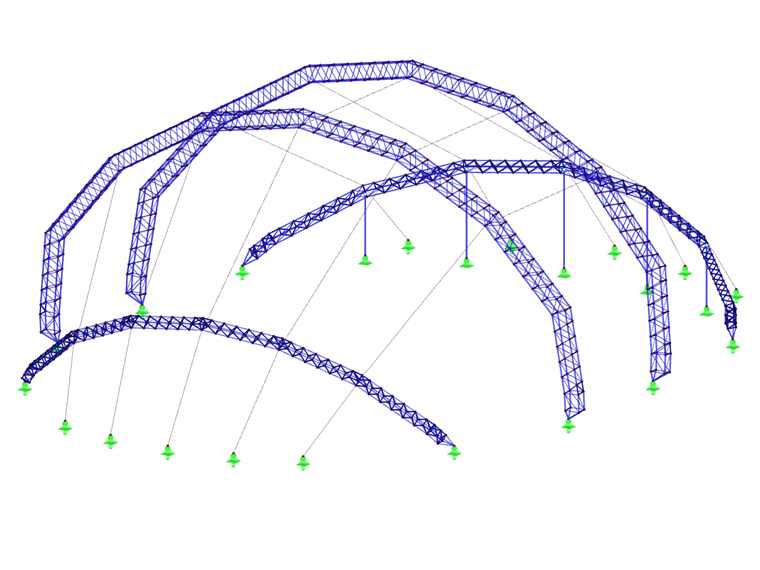
The Apollo Theater’s main structure is formed with 4 arch trusses. Hanging from these elements is an approximate 52743 ft² membrane made of PVC-coated polyester fabric type III. The two slightly inclined center trusses carry the primary load of the 240 ft long tent structure. These main trusses have a span of 183 ft and a height of 89 ft. The 36 ft high smaller lateral trusses in the foyer and backstage area are set at a higher inclination.
The interior includes a projection dome above a surrounding timber wall. This dome has a diameter of 151 ft and a height of 49 ft. It is suspended from the two main arches with elastic cables. This suspension stiffness is extremely low to allow the prestressing force to change only slightly if the outer shell is deformed (e.g. due to strong wind). The projection dome membrane consists of lightweight PVC-coated polyester fabric with micro-perforations, which absorbs about 65% of the sound.
Located under the foyer arch are 32 ft long facade supports with an ETFE cushion covering. The columns resist pressure loads only from the foyer arch. In the case of uplift loads, elongated holes provide decoupling.
The foundation for the arches includes large steel plates with 2.36 x 78.74 in piles. The plates can be used to compensate for height differences up to 19.69 in. The piles were designed according to EN 13782 and verified in a pullout test.
Within one short year, the planning, production and assembly of an unmatched temporary tent structure was completed.
Project Location
USAKeywords
Membrane Steel Aluminum Truss Theater Temporary Mobile
Write Comment...
Write Comment...
Contact us
Do you have questions or need advice?
Contact our free e-mail, chat, or forum support or find various suggested solutions and useful tips on our FAQ page.

New
In RF-/FOUNDATION Pro, the user can freely select the proportion of the relieving soil pressure by means of the factor kred.
SHAPE-THIN determines the effective cross-sections according to EN 1993-1-3 and EN 1993-1-5 for cold-formed sections. You can optionally check the geometric conditions for the applicability of the standard specified in EN 1993‑1‑3, Section 5.2.
The effects of local plate buckling are considered according to the method of reduced widths and the possible buckling of stiffeners (instability) is considered for stiffened sections according to EN 1993-1-3, Section 5.5.
As an option, you can perform an iterative calculation to optimize the effective cross-section.
You can display the effective cross-sections graphically.
Read more about designing cold-formed sections with SHAPE-THIN and RF-/STEEL Cold-Formed Sections in this technical article: Design of a Thin-Walled, Cold-Formed C-Section According to EN 1993-1-3.
- I am trying to manually check the deformations from the CRANEWAY add-on module. However, I obtain great deviations. How to explain the differences?
- What should be considered when using a failure of columns under tension in the RF‑/DYNAM Pro – Equivalent Loads add-on module?
- Why is there no stability analysis displayed in the results despite the activation of the stability analysis in RF‑/STEEL EC3?
- How can I model and design a crane runway girder with Dlubal Software?
- How do I model a suspended membrane roof structure with line supports?
- Is it possible to set user-defined values when viewing solid stress results?
- How do I model a tent roof with two cone tips?
- Why do I get large differences for the design of a longitudinally stiffened buckling panel in comparison with the German and Austrian National Annex?
- How can I create a curved or arched section?