


When selecting a nodal support or a support connection on a reinforced concrete slab, the punching load can be derived directly from the support force or from the internal forces of the support. However, if you select a node on a wall corner or a wall end for the design, the punching load cannot be determined directly from the support force or from the surface internal forces in the connected walls.
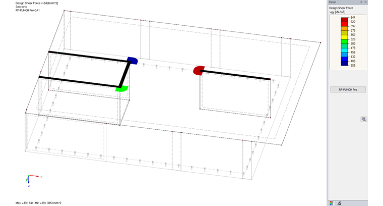
Determination of Punching Load on Wall End
Generally, the punching load cannot be determined from the support force or surface internal forces of the connected walls, but from the surface internal forces of the slab for which the punching shear design is to be performed. This approach has the advantage of avoiding the influence of singular results directly on the node to the greatest possible extent. Furthermore, this way of determining loads also allows you to consider the punching shear of a pure line load (pure load from the connected wall surface).
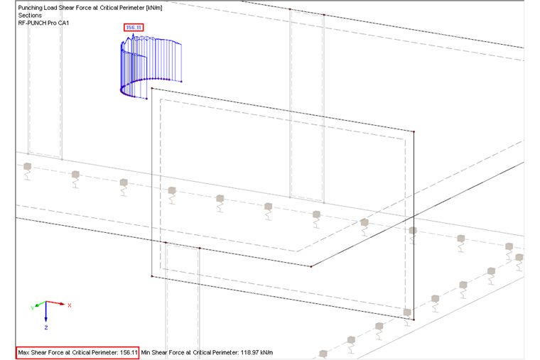
When selecting a point of punching shear, RF‑PUNCH Pro generates the basic control perimeter at a distance of 2.0d according to [1], Sect. 6.4.2.
To determine the punching load, a section is created in the module so the surface internal forces from RFEM can be measured out at the control perimeter. The surface internal force vmax,b from RFEM is used to determine the punching load. The definition of the surface internal force vmax,b is described in [2], Chapter 8.15 Surfaces – Principal Internal Forces.
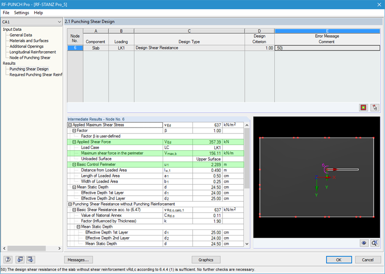
The option titled "Unsmoothed shear force over the critical perimeter" is preset in RF‑PUNCH Pro as a default setting for determining the punching load on wall ends and corners. This means that for the applied shear force determination, the maximum value is assigned along the control perimeter.
The applied shear force VEd results from:
VEd = basic control perimeter length ∙ maximum shear force at the critical perimeter
VEd = u1 ∙ vmax,b
VEd = 2.289 m ∙ 156.11 kN/m = 357.34 kN
Verification of Determined Punching Load
The punching load VEd determined in the add‑on module can be verified by creating a line in the basic control perimeter where a new section is defined. This way, you can visualize the shear force distribution along the perimeter in the RFEM graphic window or in the result diagram of the section.
The following graphic displays the result diagram of the shear force vmax,b determined in RFEM. The result diagram can help you retrace the applied shear force VEd calculated in RF‑PUNCH Pro.
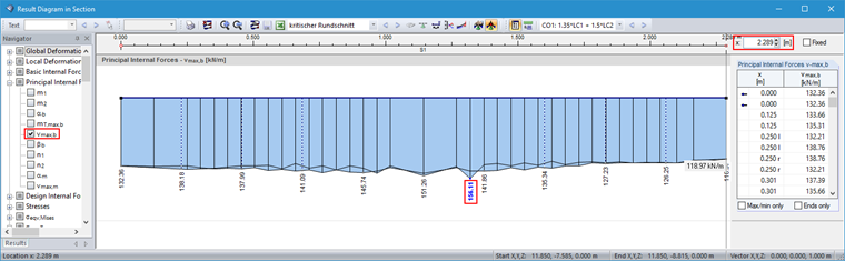
As already mentioned, the unsmoothed shear force over the critical perimeter is applied by default to determine the punching load in RF‑PUNCH Pro. Since the maximum value of the shear force is already applied along the control perimeter, the load increment factor ß is set to 1.00 for further design.
Considering Load Increment Factor ß
As an alternative, you can also select the option of smoothed shear force distribution over the critical perimeter in RF‑PUNCH Pro in order to determine the applied shear force VEd. Thus, the applied shear force is determined using the "smoothed" shear force vmax,b,average.
In this case, the load increment factor ß will be considered in the further design process. You can determine the load increment factor by using the fully plastic shear stress distribution according to 6.4.3 (3), or the constant coefficients according to 6.4.3 (6). In addition to these options for determining the load increment factor β, RF‑PUNCH Pro provides the alternative user‑defined load increment factor.