


When selecting the “2D | Constrained Modulus Method” type of soil representation, springs are created at the foundation base to simulate the bedding stiffness of the soil defined in situ. After selecting this type, additional settings appear to define the 2D soil parameters. The following image shows the input dialog box with the numbered options.

Assignment
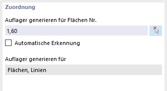
1 – Selecting Surfaces to Support
You can enter surfaces on which the supports are to be arranged in the text box or select them graphically using the button next to the text box. Additionally, you can select the “Automatic detection” check box to have RFEM detect the surfaces to be supported.
2 – Generating Supports
The following point specifies for which support types (nodes, line, and surface supports) should be spring stiffnesses generated. Currently, the Surface and Line base types are set here.
Background information on the constrained modulus method and the determination of edge springs is provided in the corresponding section of Theoretical Principles.
Parameters
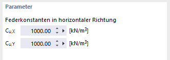
3 – Spring Constants in Horizontal Direction
The input boxes assigned to this item define the translational elastic constants in the horizontal direction that are assigned to the generated support conditions.
Options

4.1 – Nonlinearity / Failure Under Tension
By selecting this check box, nonlinearities are assigned to the generated support conditions, which lead to failure under tension perpendicular to the supported surface.
4.2 – Spring constants in horizontal direction
The text boxes assigned to this point define the translational elastic constants in the horizontal direction that are assigned to the generated support conditions.
4.3 – Generating Soil Solids
This option controls the determination of the soil structure for the entire surface to be extended.
- Generate soil solids – inactive
If the option is inactive, the layering of the soil is determined internally from the boreholes. This solution does not provide any insight into the generated layering. For massifs of large dimensions with layers of very small thickness at the same time, the solution may be more favorable in terms of the required performance in the calculation preparation.
- Generate soil solids – active
If the option is inactive, the layering of the soil is determined from the boreholes by generating the soil solids. This solution allows for insight into the generated layering. As the solids are meshed, this procedure may be less favorable in terms of the required performance in the calculation preparation.
The text box is not activated by default. The meaning of the “Generate soil solids” option is displayed in the image below.

4.4 – Deactivating Shear Stiffness
This option allows you to control the shear spring stiffness component Cv,xz or Cv,yz for the generated surface supports. These can be taken into account and determined in the tension of the constrained modulus method.
If required, however, the shear spring stiffness can be set to zero so that only the normal elastic foundation coefficient in the z-direction Cu,z is used.
The following image illustrates the effect of the “Generate soil solids” option for the elastic foundation coefficient from the constrained modulus method.

Generated Supports
The following image shows an example of the supports generated from the settings of the 2D soil parameters.

