


In the dialog box for defining members, several member types are available for selection. The properties of the member types are described in the Members – Main chapter of the RFEM 6 manual. In addition to the member types provided by RFEM, the Geotechnical Analysis add-on offers the member types "Pile" and "Anchor", which will be described in detail in the following.
Piles
The following image shows how the “Pile” member type can be selected in the dialog box:

Piles have the following options
- Hinges
- Eccentricities
- Result intermediate points, and
- Deactivate for calculation
More information about these options is available in the general chapter on members in the RFEM 6 manual. In the "Section" tab, you can assign the cross-section and the material as usual.
Skin Friction and Peak Pressure
Piles are supported by skin friction and peak pressure in the soil solid. These resistances are entered in the "Pile resistance type" object.
If "Pile" is selected as a member type, the additional "Pile" tab appears where you can assign ((1) in the image), create ((2) in the image), or edit ((3) in the image) the pile resistance type.

The pile resistance type dialog box is shown in the image below.
.png?mw=760&hash=282ec78b53706f9f64d291d2f302e26063d71849)
In the upper section, the resistance values due to the pile skin friction can be defined. Two types of distribution of the skin friction resistance are available for selection. Trapezoidal and varying.
- The Trapezoidal setting allows you to enter the resistance at the pile head as a start value, and at the pile base as an end value. In the area in between, a linear distribution of the resistance values is assumed between the start and the end.
- The Varying setting allows you to divide the resistance into layers, whereby each layer has a linear distribution.
You have to define the shear strength as well as the shear stiffness for the start, end, or x-locations.
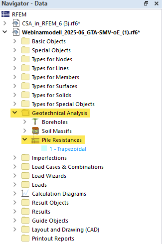
The pile resistance type is stored in the "Geotechnical Analysis" folder in the Navigator and can be opened, edited, or created directly from there.
Meshing
To create the finite element mesh of the model, the following requirements need to be considered for piles.
Independent mesh
The piles require a mesh that is independent of the solid mesh of the in-situ soil. To ensure that the mesh is created independently, the line of the pile should first be assigned as an integrated object of the soil solid. This can be controlled by the setting in the soil solid as shown below.

Nodes of Pile Head
It is important to note that the pile head node should not be defined as an integrated object of the terrain surface, as this can lead to incorrect load introduction and calculation errors. You can check this as displayed in the following image.

FE size
It is recommended to use an element size for the in-situ soil that corresponds to the maximum size of the pile diameter. This can be set using the global mesh settings or the solid mesh refinement.
Furthermore, the piles should be more finely meshed than the underlying soil solids. The element size can correspond to half the element size of the soil solid mesh. For this, you can assign a mesh refinement to the lines of the piles.
Anchor
The following image shows how you can select the "Anchor" member type in the dialog box:

By selecting the “Anchor” member type, a special tab appears in the input dialog box, which is displayed in the following image:

Here, you can edit the properties of the individual components of a soil anchor separately. On the one hand, these are tendons that are unbonded to the surrounding soil and, on the other hand, grout bodies with bond properties. Under (1), you can select the position on the assigned line, where i corresponds to the start part and j corresponds to the end part. This is followed by (2) the cross-section of the tension member. In the lower part of the dialog box, you can edit the properties of the grout body. Under (3), you can define the bond length either as an absolute value or as a percentage (you can switch it on using the percent symbol). Subsequently, you can select the cross-section under (4) and the pile resistance type under (5).
After selecting the "Anchor" member type, the individual components are automatically generated as separate members according to the selected bond length. This creates two new members: the grout body as the "Pile" member type, and the unbonded tendon as the "Tension" member type. The following image shows this:

You can switch the display of the generated members in the “Navigator – Display” using the “Objects generated by anchors” option under “Model | Basic Objects | Basic Objects | Members”, as shown in the following image:


