We provide hints and tips to help you get started with the RFEM program.
CP 001100 | Reconstruction of Güsen Road Bridge B 10 over the Elbe-Havel Canal, Germany
Video
First Steps with RFEM
Description
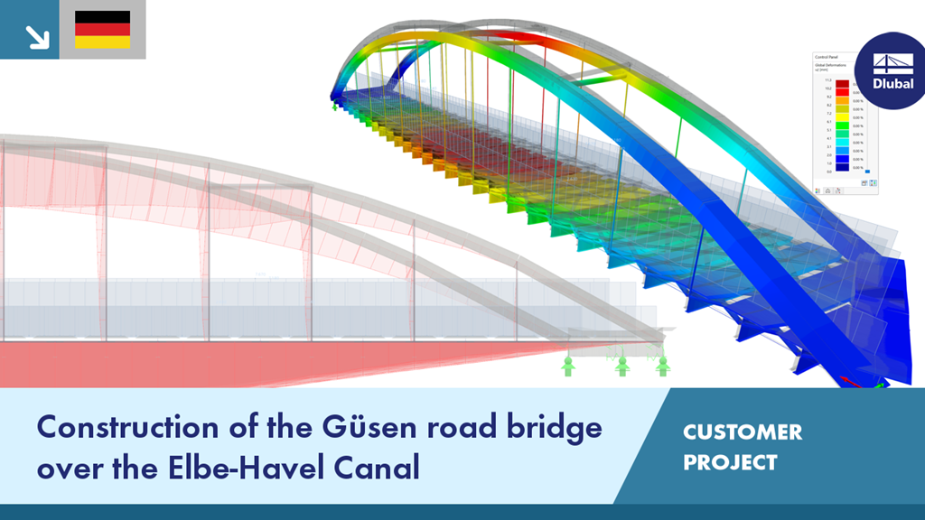
The new Güsen road bridge B 10 is a tied‑arch bridge with an orthotropic roadway slab. The clear width between bridge abutments is about 301.9 ft and the bridge width is almost 46 ft wide.
The arches are made of welded box sections. A horizontal stiffening of the arches is achieved by 4 crossbeams made of steel round tubes (portal effect). Both stringers of the bridge are suspended with 12 round members of d = 4 inches each.
The engineers from grbv used the RSMOVE add‑on module to generate moving loads in RSTAB. Also, many cross‑sections were created in the cross‑section properties software SHAPE‑THIN. The bridge model was converted to RFEM 6 for a presentation video.
Keywords
Dlubal Customer Project Bridge construction Steel bridge Steel Bridge Steel structure Member BIM BIM structural analysis Civil engineering Software for civil engineers Customer Project Project with Dlubal Software Dlubal Practical Example
Links
Write Comment...
Write Comment...
Contact Us
Do you have any questions about our products or which are best suited for your design projects? Contact us via phone, email, or chat or find suggested solutions and useful tips on our FAQ page available 24/7.

Consideration of Construction Stages in RFEM 6
The calculation of complex structures by means of finite element analysis software is generally performed on the entire model. However, the construction of such structures is a process carried out in multiple stages where the final state of the building is achieved by combining the separate structural parts. To avoid errors in the calculation of overall models, the influence of the construction process must be considered. In RFEM 6, this is possible by using the Construction Stages Analysis (CSA) add-on.
-
Can I also use user-defined materials in RF‑/PLATE‑BUCKLING?
- How do I set a release for warping?
- How can I define a warping spring or a warping restraint?
- At which point on a cross-section are the supports and loads assumed for the calculation with warping torsion?
- The limit stress is activated, but my stress ratio is “non-designable” in the Stress-Strain Analysis add-on. What could be the reason?
- How do I set a release for warping?