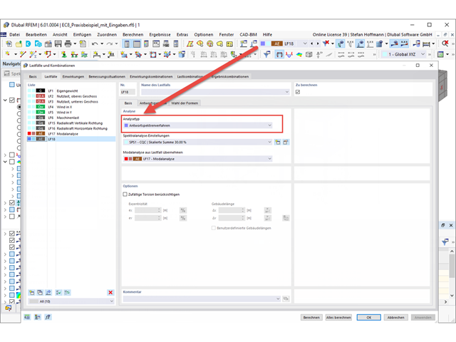
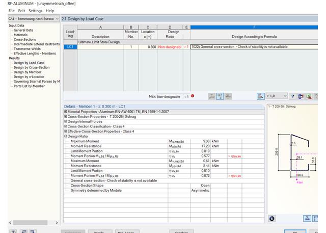
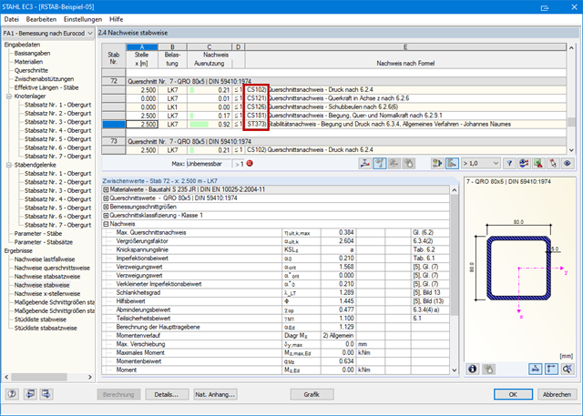
I am trying to design an open, unsymmetric aluminum cross-section in RF‑/ALUMINUM and I am get the warning "Non-designable - 1022) General cross-section — Check of stability is not available". What is the reason?
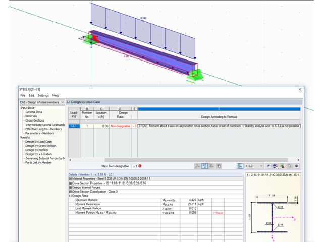
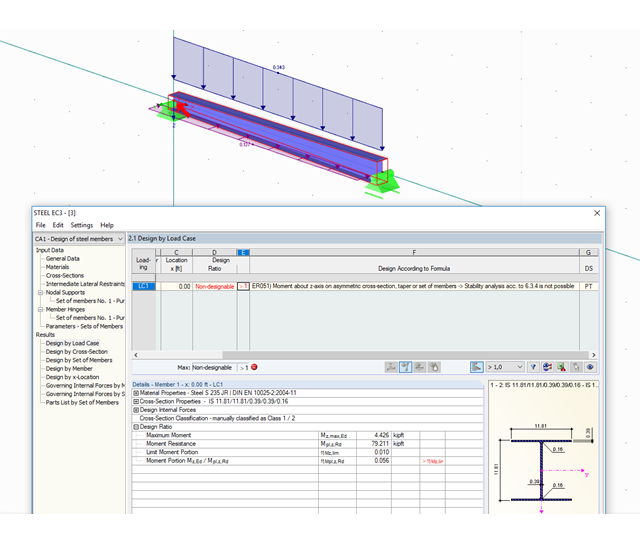
I am designing a tapered beam and I get the message "Non-designable: ER051 Moment about z-axis on asymmetric cross-section, taper, or set of members". Why?
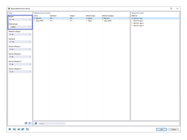
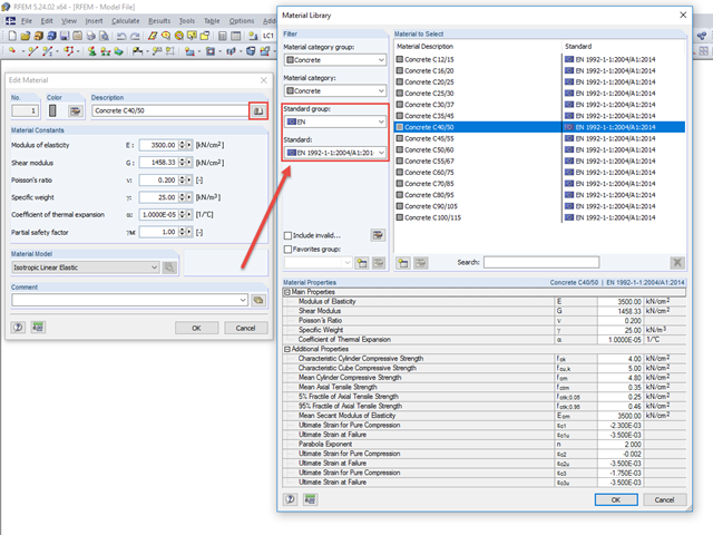
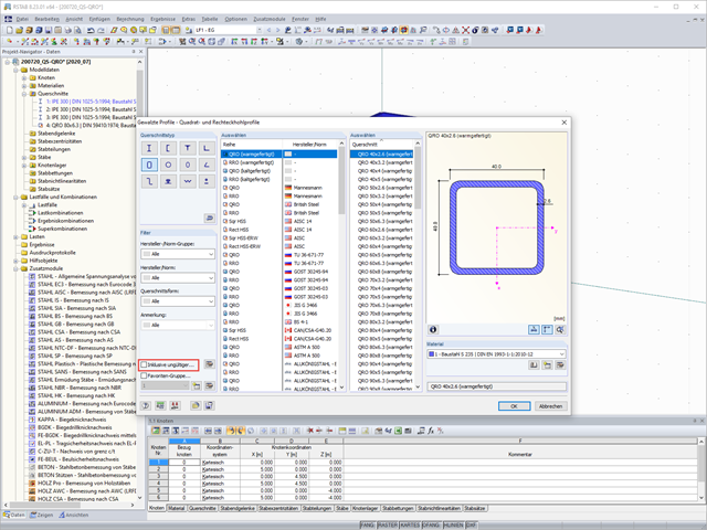
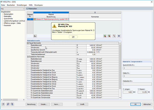
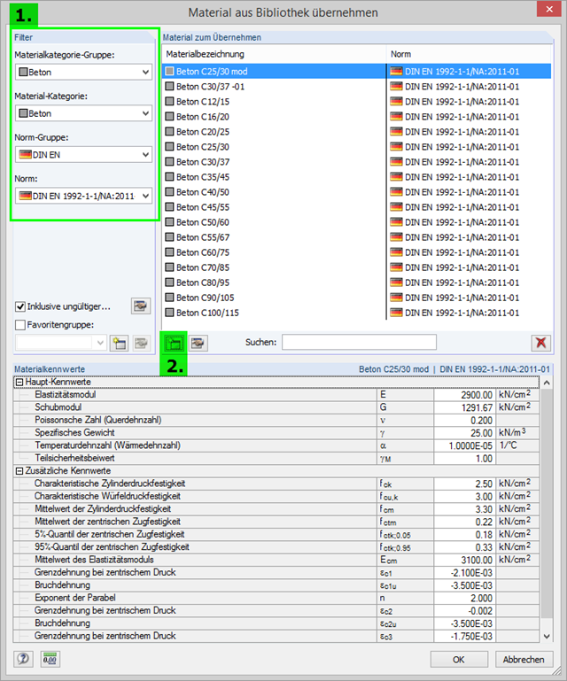
Which filter settings should be selected in the material library for concrete in order to perform design in RF‑CONCRETE according to the Swedish National Annex? In RFEM, no Swedish standard group is available for the selection.
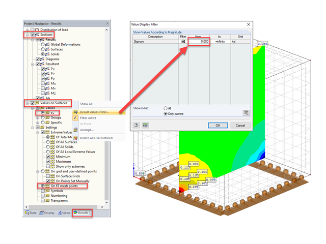
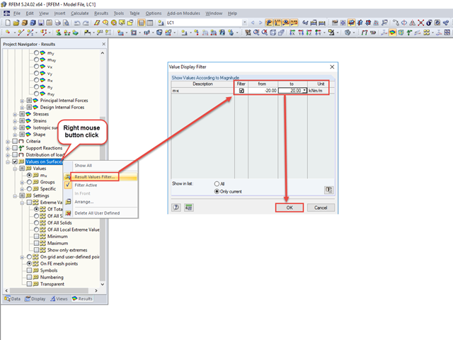
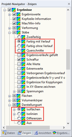
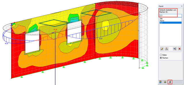
In the filter settings for the values on surfaces, you can display a certain range of results and hide the rest. How can I hide a certain range of values and display the rest?
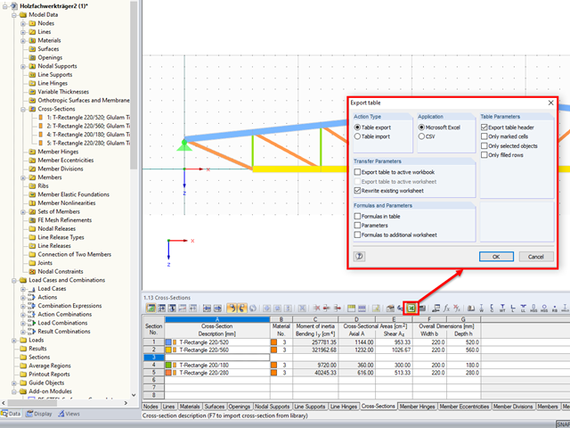
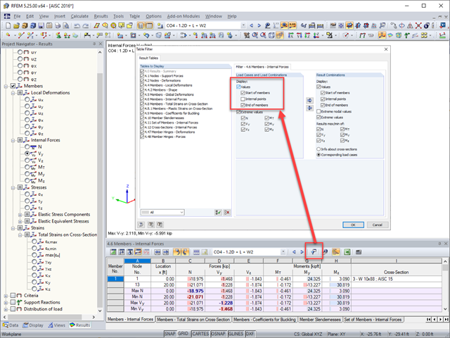
For the connection design, I would like to display the resulting internal forces at the start and end nodes of the beam in a table. However, the beam consists of several members, which leads to a very confusing tabular display. How can I optimize it?
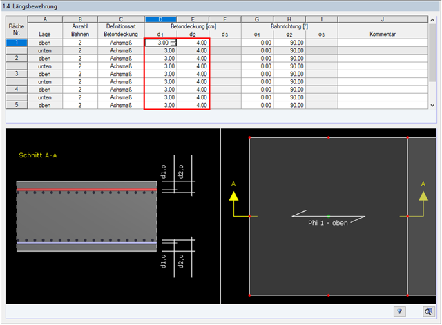
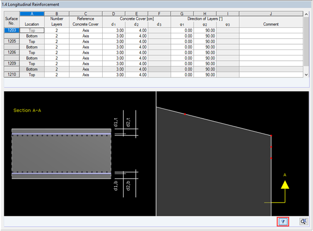
In Window "1.4 Longitudinal Reinforcement", all the surfaces are always displayed, although I do not want to check punching for all of the surfaces. Is it possible to display only the designed surfaces?
I am designing a set of members with a uniform, double-symmetric cross-section and I get the warning "Non-designable: ER051 Moment about z-axis on asymmetric cross-section, taper, or set of members". Why?
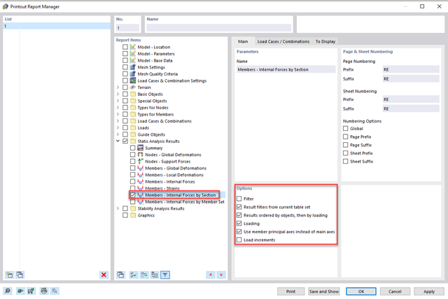
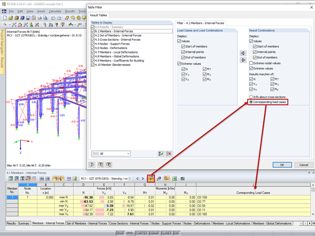
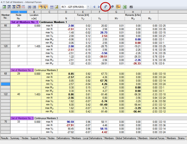
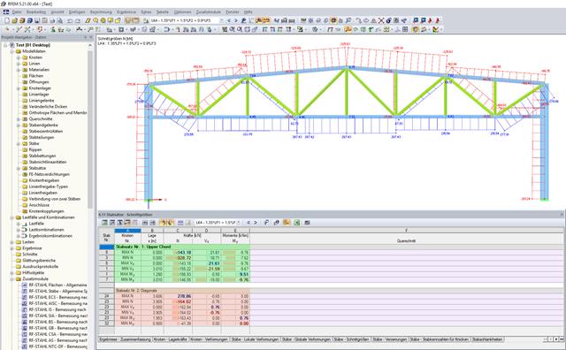
Is it possible for the program to create a table that shows the maximum internal force combinations of several members? For example, for the upper chord of a truss and for the struts.
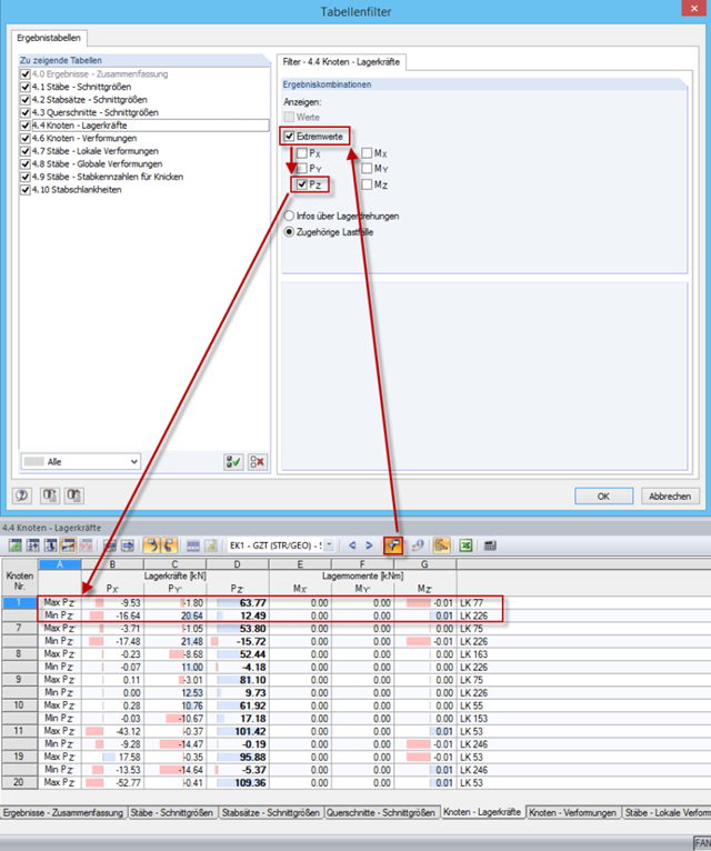
For my result evaluation, the extreme values of the vertical support forces with the corresponding horizontal forces from a result combination are required for several support nodes. Is it possible to set this in the program?
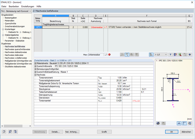
When designing a beam, I would like to neglect the torsion included in the stability analyses using the filters described in Knowledge Base article #001498.
I define the filter, but the torsion warning appears at the same x‑location again. Do the design internal forces change, or why is that?
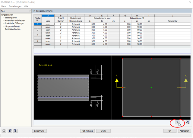
In RF‑PUNCH Pro, Window "1.4 Longitudinal Reinforcement" shows all surfaces connected to the nodes selected for design. For example, in a punching shear design on a wall corner, the surfaces that actually represent the walls are also defined. I can also define a longitudinal reinforcement for these surfaces. Is this reinforcement applied somehow? Why do I see these surfaces in Window 1.4?