65 Results
View Results:
Sort by:

Moment frame design according to AISC 341-16 is now possible in the Steel Design add-on of RFEM 6. The seismic design result is categorized into two sections: member requirements and connection requirements. This article covers the required strength of the connection. An example comparison of the results between RFEM and the AISC Seismic Design Manual [2] is presented.

Both the determination of natural vibrations and the response spectrum analysis are always performed on a linear system. If nonlinearities exist in the system, they are linearized and thus not taken into account. They are caused by, for example, tension members, nonlinear supports, or nonlinear hinges. This article shows how you can handle them in a dynamic analysis.

To be able to evaluate the influence of local stability phenomena of slender structural components, RFEM 6 and RSTAB 9 provide you with the option of performing a linear critical load analysis on the cross-section level. The following article explains the basics of the calculation and the result interpretation.

The CSA S16:19 Stability Effects in Elastic Analysis method in Annex O.2 is an alternative option to the Simplified Stability Analysis Method in Clause 8.4.3. This article will describe the requirements of Annex O.2 and application in RFEM 6.

The design of cold-formed steel members according to the AISI S100-16 is now available in RFEM 6. Design can be accessed by selecting “AISC 360” as the standard in the Steel Design add-on. “AISI S100” is then automatically selected for the cold-formed design (Image 01).

Windbreak structures are special types of fabric structures which protect the environment from harmful chemical particles, abate wind erosion, and help to maintain valuable sources. RFEM and RWIND are used for wind-structure analysis as one-way fluid-structure interaction (FSI).
This article demonstrates how to structural design windbreak structures using RFEM and RWIND.

The advantage of the RFEM 6 Steel Joints add-on is that you can analyze steel connections using an FE model for which the modeling runs fully automatically in the background. The input of the steel joint components that control the modeling can be done by defining the components manually, or by using the available templates in the library. The latter method is included in a previous Knowledge Base article titled “Defining Steel Joint Components Using the Library". The definition of parameters for the design of steel joints is the topic of the Knowledge Base article “Designing Steel Joints in RFEM 6".

Steel connections in RFEM 6 are defined as an assembly of components. In the new Steel Joints add-on, universally applicable basic components (plates, welds, auxiliary planes) are available for entering complex connection situations. The methods with which connections can be defined are considered in two previous Knowledge Base articles: “A Novel Approach to Designing Steel Joints in RFEM 6" and “Defining Steel Joint Components Using the Library".

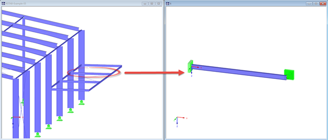
The stability checks for the equivalent member design according to EN 1993-1-1, AISC 360, CSA S16, and other international standards require consideration of the design length (that is, the effective length of the members). In RFEM 6, it is possible to determine the effective length manually by assigning nodal supports and effective length factors or, on the other hand, by importing it from the stability analysis. Both options will be demonstrated in this article by determining the effective length of the framed column in Image 1.

This technical article presents some basics for using the Torsional Warping add-on (7 DOF). It is fully integrated into the main program and allows you to consider the cross-section warping when calculating member elements. In combination with the Stability Analysis and Steel Design add-ons, it is possible to perform the lateral-torsional buckling design with internal forces according to the second-order analysis, taking imperfections into account.

Very small torsional moments in the members to be designed often prevent certain design formats. In order to neglect them and still perform the designs, you can define a limit value in RF‑/STEEL EC3 from which torsional shear stresses are taken into account.

Structure stability is not a new phenomenon when referring to steel design. The Canadian steel design standard CSA S16 and the most recent 2019 release are no exception. Detailed stability requirements can be addressed with either the Simplified Stability Analysis Method in Clause 8.4.3 or, new to the 2019 standard, the Stability Effects in Elastic Analysis method provided in Annex O.

- 000945
- Add-on Modules
- RF-FRAME-JOINT Pro 5
-
- JOINTS Steel | Column Base 8
- JOINTS Steel | DSTV 8
- JOINTS Steel | Pinned 8
- JOINTS Steel | Rigid 8
- JOINTS Steel | SIKLA 8
- JOINTS Steel | Tower 8
- JOINTS Timber | Steel to Timber 8
- JOINTS Timber | Timber to Timber 8
- RF-JOINTS Steel | SIKLA 5
- RF-JOINTS Steel | Column Base 5
- RF-JOINTS Steel | DSTV 5
- RF-JOINTS Steel | Pinned 5
- RF-JOINTS Steel | Rigid 5
- RF-JOINTS Steel | Tower 5
- RF-JOINTS Timber | Steel to Timber 5
- RF-JOINTS Timber | Timber to Timber 5
- FRAME-JOINT Pro 8
- Steel Structures
- Timber Structures
- Steel Connections
- Eurocode 3
- Eurocode 5
In addition to the result tables, you can create three-dimensional graphics in RF‑/FRAME‑JOINT Pro and RF‑/JOINTS. This is a realistic representation of a connection to scale.

The RF‑/STEEL EC3 add-on module automatically transfers the buckling line to be used for the flexural buckling analysis for a cross-section from the cross-section properties. The assignment of the buckling line can be adjusted manually in the module input for general cross-sections in particular, as well as for special cases.

When optimizing cross-sections in the add-on modules, you can also select arbitrarily defined cross-section favorites lists - in addition to the cross-sections from the same cross-section series as the original cross-section.

When connecting tension-loaded components with bolted connections, the cross-section reduction due to the bolt holes must be taken into account in the ultimate limit state design. This article describes how the design of the tension resistance according to DIN EN 1993‑1‑1 can be performed with the net cross-section area of the tension member in the RF‑/STEEL EC3 add-on module.

In the RF‑/HSS add‑on module, you can analyze the connections for nodes at which hollow sections join. RF‑/HSS performs the ultimate limit state designs according to EN 1993‑1‑8:2005.

Table 3.1 of EN 1993‑1‑8:2010‑12 defines the nominal values of the yield strength and the ultimate limit strength of bolts. The bolt classes given here are 4.6, 4.8, 5.6, 5.8, 6.8, 8.8, 10.9. The note for this table states that the National Annex may exclude certain bolt classes. For the NA of Germany, these are the bolt classes 4.8, 5.8, and 6.8.

According to Clause 6.2.2 (6) of EN 1993‑1‑8:2010‑12, you can apply friction using the friction coefficient to design the shear capacity.

This technical article deals with the design of structural components and cross-sections of a welded truss girder in the ultimate limit state. Furthermore, the deformation analysis in the serviceability limit state is described.

Closed circular cross-sections are ideal for welded truss structures. The architecture of such constructions is popular when designing transparent roofs. This article shows the special features of the connection design using hollow sections.

Designing rigid end plate connections is difficult for four-row connection geometries and multi-axis bending stresses, because there are no official design methods.

This technical article deals with the stability analysis of a roof purlin, which is connected without stiffeners by means of a bolt connection on the lower flange to have a minimum manufacturing effort.

According to Clause 3.2.2, EN 1993-1-3 allows the use of an average increased yield strength fya of a cross-section due to strain hardening.

This technical article analyzes the effects of the connection stiffness on the determination of internal forces, as well as the design of connections using the example of a two-story, double-spanned steel frame.

In this technical article, a hinged column with a centrally acting axial force and a line load acting on the strong axis will be designed by means of the RF-/STEEL EC3 add-on module according to EN 1993-1-1.

A welded connection of an HEA cross-section under biaxial bending with axial force will be designed. The design of welds for the given internal forces according to the simplified method (DIN EN 1993-1-8, Clause 4.5.3.3) by means of SHAPE-THIN will be performed.
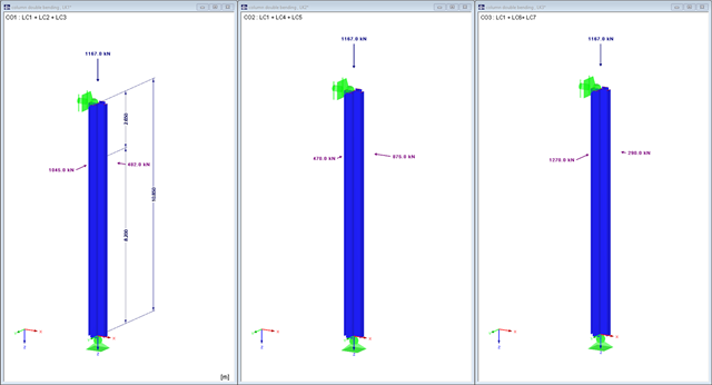
This example will show what you should consider when you perform column design for bending and compression with regard to the internal forces from load combinations and result combinations.

The fire resistance design can be performed according to EN 1993-1-2 in RF-/STEEL EC3. The design is carried out according to the simplified calculation method for the ultimate limit state. Claddings with different physical properties can be selected as fire protection measures. You can select the standard temperature-time curve, the external fire curve, and the hydrocarbon curve to determine the gas temperature.
The input windows in RF-/STEEL EC3 distinguish between the flexural and lateral-torsional buckling analyses. In the following text, an example will show the parameters for lateral-torsional buckling.