58 Results
View Results:
Sort by:

RF-/DYNAM Pro - Equivalent Loads allows you to determine the loads due to equivalent seismic loads according to the multi‑modal response spectrum method. In the example shown here, this was done for a multi‑mass oscillator.

When optimizing cross-sections in the add-on modules, you can also select arbitrarily defined cross-section favorites lists - in addition to the cross-sections from the same cross-section series as the original cross-section.

When connecting tension-loaded components with bolted connections, the cross-section reduction due to the bolt holes must be taken into account in the ultimate limit state design. This article describes how the design of the tension resistance according to DIN EN 1993‑1‑1 can be performed with the net cross-section area of the tension member in the RF‑/STEEL EC3 add-on module.

According to Clause 6.2.2 (6) of EN 1993‑1‑8:2010‑12, you can apply friction using the friction coefficient to design the shear capacity.

Table 3.1 of EN 1993‑1‑8:2010‑12 defines the nominal values of the yield strength and the ultimate limit strength of bolts. The bolt classes given here are 4.6, 4.8, 5.6, 5.8, 6.8, 8.8, 10.9. The note for this table states that the National Annex may exclude certain bolt classes. For the NA of Germany, these are the bolt classes 4.8, 5.8, and 6.8.

In the RF‑/HSS add‑on module, you can analyze the connections for nodes at which hollow sections join. RF‑/HSS performs the ultimate limit state designs according to EN 1993‑1‑8:2005.

For relatively large or relatively small surfaces, it can happen that the automatically created result values do not fit the model: In the case of large surfaces, there can be too many result values; in the case of small surfaces, too few.

In RF-/FOUNDATION Pro, the user can freely select the proportion of the relieving soil pressure by means of the factor kred.

The determined values for the influence ordinates are displayed as decimal numbers with up to six decimal places by default. This is usually sufficient for the influence lines of internal forces.

The RF‑/STEEL EC3 add-on module can perform the design of fillet welds for all parametric, welded cross-sections of the cross-section library. For this, the option must be activated in the detail settings of the module. As an alternative, you can also use a surface model for the design.

Very small torsional moments in the members to be designed often prevent certain design formats. In order to neglect them and still perform the designs, you can define a limit value in RF‑/STEEL EC3 from which torsional shear stresses are taken into account.

You can make various settings in order to achieve a clearly‑arranged display of the result values. For example, some users may not want the white background in text bubbles. You can adjust the background in "Display Properties" using the Transparent and Background color option.

- 000945
- Add-on Modules
- RF-FRAME-JOINT Pro 5
-
- JOINTS Steel | Column Base 8
- JOINTS Steel | DSTV 8
- JOINTS Steel | Pinned 8
- JOINTS Steel | Rigid 8
- JOINTS Steel | SIKLA 8
- JOINTS Steel | Tower 8
- JOINTS Timber | Steel to Timber 8
- JOINTS Timber | Timber to Timber 8
- RF-JOINTS Steel | SIKLA 5
- RF-JOINTS Steel | Column Base 5
- RF-JOINTS Steel | DSTV 5
- RF-JOINTS Steel | Pinned 5
- RF-JOINTS Steel | Rigid 5
- RF-JOINTS Steel | Tower 5
- RF-JOINTS Timber | Steel to Timber 5
- RF-JOINTS Timber | Timber to Timber 5
- FRAME-JOINT Pro 8
- Steel Structures
- Timber Structures
- Steel Connections
- Eurocode 3
- Eurocode 5
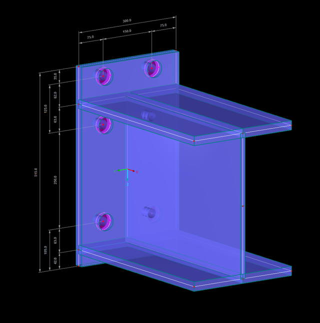
In addition to the result tables, you can create three-dimensional graphics in RF‑/FRAME‑JOINT Pro and RF‑/JOINTS. This is a realistic representation of a connection to scale.

For structural reasons, shear connections usually include fin plates or flange angles. Main and secondary beams arranged on the top edge require notching or long fin plates. Hinged end plate connections are often welded to the web.

In RF-STEEL Surfaces, it is possible to display the stresses relevant for the design of welds, for example, according to EN 1993‑1‑8, Figure 4.5. When evaluating the stress components, the local xyz-axis system of the surfaces must be considered.

The RF‑/STEEL Warping Torsion module extension of the RF‑/STEEL EC3 add‑on module allows you to design members with asymmetric cross‑sections. The new option is fully integrated in the design module and can be activated for sets of members.
![System and Loading According to [1]](/en/webimage/009455/2418877/01-en-png.png?mw=640&hash=c76563b459152b19c98197ea6ba342be89d9a5bc)
The product range of Dlubal Software contains various modules for the design of steel and timber connections. The RF-/JOINTS Steel – Column Base add-on module allows you to analyze footings of hinged or restrained steel column bases. The fastener selection, foundation geometry, and material quality are crucial for the cost-effective and safe design of the column base.

A fillet weld is the most common weld type in steel building construction. According to EN 1993-1-8, 4.3.2.1 (1) [1], fillet welds may be used for connecting structural part where the fusion faces form an angle of between 60° and 120°.

When designing bending-resistant connections from I-beams, the connection is dissolved into the individual parts. For these basic components of a joint, there are separate formula calculators for load-bearing capacity and stiffness. In RFEM and RSTAB, frame joints can be designed using the RF-/FRAME-JOINT Pro add-on module.

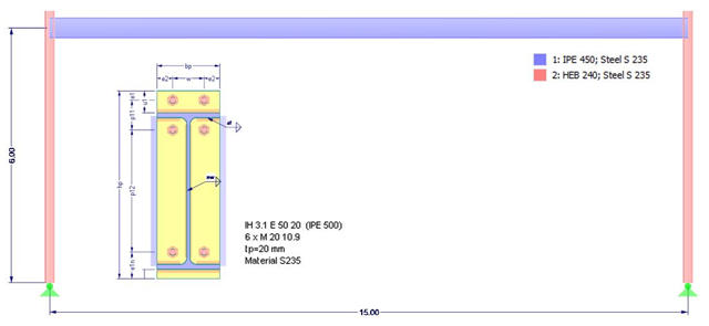
In this example, the design resistance of an end plate according to EN 1993-1-8 [1] is to be determined; the other components are not described here. To check the results, the dimensions of the connection IH 3.1 B 30 24 of Typified Connections [2] were used. S 235 material and bolts with strength 10.9 are used.

Shell buckling is considered to be the most recent and least explored stability issue of structural engineering. This is due less to a lack of research activities than to the complexity of the theory. With the introduction and further development of the finite element method in structural engineering practice, some engineers no longer have to deal with the complicated theory of shell buckling. Evidence of the problems and errors to which this gives rise is very well summarized in [1].

RFEM offers the following options to design a pinned end plate connection. First, there is the option in RF-JOINTS Steel - Pinned to enter the corresponding parameters quickly and easily to receive a documented analysis, including graphics. It is also possible to model such a connection individually in RFEM and then to evaluate or manually design the results. In the following example, the particularities of this modeling will be explained and the shear forces of the bolts will be compared to the corresponding results from RF-JOINTS Steel - Pinned.
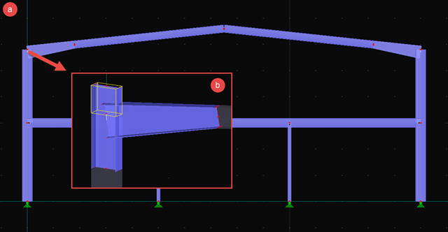
Especially if the adjacent area of connection points is to be analyzed, if the geometry and load of the connection do not correspond to the standard specifications, and/or if a model is to be analyzed using an FE model (for example, in plant engineering), the connections must also be evaluated in detail on the FE model.

Fin plate connections are a popular form of pinned steel connection and are commonly used for secondary beams in steel structures. They can be used easily in beam structures arranged on the top edge (for example, working platforms). Manufacturing expenditures in the workshop as well as the onsite assembly costs are normally manageable. The design seems to be completed easily and quickly, but it has to be put into perspective to a certain extent in the following text. Moreover, this connection type is basically possible as a pinned beam-to-beam or pinned beam-to-column connection; the former case is the more common one in design practice.
This article deals with the stiffness of standardized joints according to the DSTV (German Steel Construction Association)/DASt (German Committee for Structural Steelwork) standards, often used in steel construction, and its effects on structural analysis and design results according to DIN EN 1993-1-1.

In SHAPE-THIN, the calculation of stiffened buckling panels can be performed according to Section 4.5 of EN 1993-1-5. For stiffened buckling panels, the effective surfaces due to local buckling of the single panels in the plate and in the stiffeners, as well as the effective surfaces from the entire panel buckling of the stiffened entire panel, have to be considered.

- 001541
- Results
- RFEM 5
-
- RF-DYNAM Pro | Natural Vibrations 5
- RF-DYNAM Pro | Equivalent Loads 5
- RF-DYNAM Pro | Forced Vibrations 5
- RSTAB 8
- DYNAM Pro | Natural Vibrations 8
- DYNAM Pro | Equivalent Loads 8
- Concrete Structures
- Steel Structures
- Timber Structures
- Process Manufacturing Plants
- Power Plants
- Buildings
- Dynamic and Seismic Analysis
- ASCE 7
RFEM offers the option to perform a response spectrum analysis according to ASCE 7-16. This standard describes the determination of seismic loads for the American market. It might happen that the P-Delta effect has to be considered due to the stiffness of the entire structure in order to calculate the internal forces and carry out the design.
- 001545
- Modeling | Structure
- RFEM 5
-
- RF-FRAME-JOINT Pro 5
- RF-JOINTS Timber | Timber to Timber 5
- RF-JOINTS Timber | Steel to Timber 5
- RF-JOINTS Steel | Rigid 5
- RF-JOINTS Steel | DSTV 5
- RF-JOINTS Steel | Pinned 5
- RF-JOINTS Steel | Tower 5
- RF-JOINTS Steel | SIKLA 5
- RF-JOINTS Steel | Column Base 5
- Steel Structures
- Mechanical Engineering
- Cranes and Craneways
- Towers and Masts
- Process Manufacturing Plants
- Steel Connections
- Finite Element Analysis
- Structural Analysis & Design
- Eurocode 3
- DIN 18800
With RF-/FRAME-JOINT Pro, you can design frame joints according to DIN 18800 or Eurocode 3. When dealing with non-standardized joints or when a deeper insight into the connection and its behavior is required, modeling as a surface model is ideal. This article will show, in principle, how this kind of model is created.

The critical factor for lateral-torsional buckling or the critical buckling moment of a single-span beam will be compared according to different stability analysis methods.

DIN EN 1998-1 with the National Annex DIN EN 1998-1/NA specifies how to determine seismic loads. The standard applies to structural engineering in seismic areas.