159 Results
View Results:
Sort by:

In addition to the basic combination rules of EN 1990, there are other combination conditions for actions on road bridges specified in EN 1991‑2 that must be taken into account. RFEM and RSTAB provide automatic combinatorics that can be activated in the General Data when selecting the standard EN 1990 + EN 1991‑2. The partial safety factors and combination coefficients depending on the action category are preset when selecting the respective National Annex.

Silos are used as large containers for storage of bulk materials such as agricultural products or source materials as well as intermediates of industrial production. The structural engineering of such structures requires a precise knowledge of the stresses due to particulate solids in the building structure. The standard EN 1991‑4 "Actions on Silos and Tanks" [1] provides the general principles and requirements for determining these actions.

In RF‑/FOUNDATION Pro, the available reinforcing steel diameters can be adjusted by the user. The adjustment of the available rebar diameters works similarly to the same function in the RF‑/CONCRETE (Members) and RF‑/CONCRETE Columns add‑on modules.

In RF‑/FOUNDATION Pro, reinforcement drawings are displayed after designing the foundation, where you can record all necessary structures of the reinforcement steel.

For relatively large or relatively small surfaces, it can happen that the automatically created result values do not fit the model: In the case of large surfaces, there can be too many result values; in the case of small surfaces, too few.

The design of an Ordinary Concentrically Braced Frame (OCBF) and a Special Concentrically Braced Frame (SCBF) can be carried out in the Steel Design add-on of RFEM 6. The seismic design result according to AISC 341-16 and 341-22 is categorized into two sections: Member Requirements and Connection Requirements.

The Steel Design add-on in RFEM 6 now offers the ability to perform seismic design according to AISC 341-16 and AISC 341-22. Five types of seismic force-resisting systems (SFRS) are currently available.

Moment frame design according to AISC 341-16 is now possible in the Steel Design add-on of RFEM 6. The seismic design result is categorized into two sections: member requirements and connection requirements. This article covers the required strength of the connection. An example comparison of the results between RFEM and the AISC Seismic Design Manual [2] is presented.

The three types of moment frames (Ordinary, Intermediate, Special) are available in the Steel Design add-on of RFEM 6. The seismic design result according to AISC 341-16 is categorized into two sections: member requirements and connection requirements.

The three types of moment frames (Ordinary, Intermediate, Special) are available in the Steel Design add-on of RFEM 6. The seismic design result according to AISC 341-22 is categorized into two sections: member requirements and connection requirements.

The AISC 360-16 steel standard requires stability consideration for a structure as a whole and each of its elements. Various methods for this are available, including direct consideration in the analysis, the effective length method, and the direct analysis method. This article will highlight the important requirements from Ch. C [1] and the direct analysis method to be incorporated in a structural steel model along with the application in RFEM 6.

Utilizing the RF-STEEL AISC add-on module, steel member design is possible according to the AISC 360-16 standard. The following article will compare the results between calculating lateral torsional buckling according to Chapter F and Eigenvalue Analysis.
Requirements for the design of structural stability are given in the AISC 360 – 14th Ed. Chapter C. In particular, the direct analysis method provisions, previously located in Appendix 7 of the AISC 360 – 13th Ed., are described in detail. This method is considered an alternative to the effective length method, which in turn eliminates the need for effective length (K) factors other than 1.0.

The design of cold-formed steel members according to the AISI S100-16 is now available in RFEM 6. Design can be accessed by selecting “AISC 360” as the standard in the Steel Design add-on. “AISI S100” is then automatically selected for the cold-formed design (Image 01).

Custom sections are often required in cold-formed steel design. In RFEM 6, the custom section can be created using one of the “Thin-Walled” sections available in the library. For other sections that do not meet any of the 14 available cold-formed shapes, the sections can be created and imported from the standalone program, RSECTION. For general information on AISI steel design in RFEM 6, refer to the Knowledge Base article provided at the end of the page.
.png?mw=640&hash=8fd04a597cecae2e434980ce79fc626815a5d98a)
The Aluminum Design Manual (ADM) 2020 was released in February 2020. The ADM 2020 gives guidance for both the allowable strength design (ASD) and load and resistance factor design (LRFD) for aluminum members to ensure reliability and safety for all aluminum structures. This latest standard was integrated in the RFEM/RSTAB add-on module RF-/ALUMINUM ADM. The text below will highlight the applicable updates relevant to the Dlubal programs.
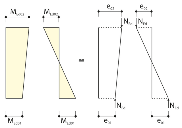
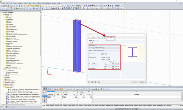
When calculating the internal forces for the buckling analysis with the method based on nominal curvature in RF‑CONCRETE Columns, the required eccentricities have to be determined.

RF‑/FOUNDATION Pro introduced the geotechnical design of single foundations according to EN 1997‑1 in RFEM 5 and RSTAB 8. Depending on the National Annex preset in the add‑on module, you can determine the bearing resistance using Approach 2 or 3 in compliance with EN 1997‑1 up to Version x.04.0108.
When determining the minimum reinforcement for the serviceability limit state according to 7.3.2, the applied effective tensile strength fct,eff has a significant influence on the determined amount of reinforcement. The following article gives an overview about determining the effective tensile strength fct,eff and the input options in RF-CONCRETE.

The automatic surface reinforcement design process determines a surface reinforcement that covers the required amount of reinforcement.

When defining the effective slab width of T-beams, RFEM provides the predefined widths that are determined as 1/6 and 1/8 of the member length. A more detailed explanation on these two factors is given below.

This article describes how a flat slab of a residential building is modeled in RFEM 6 and designed according to Eurocode 2. The plate is 24 cm thick and is supported by 45/45/300 cm columns at distances of 6.75 m in both the X and Y directions (Image 1). The columns are modeled as elastic nodal supports by determining the spring stiffness based on the boundary conditions (Image 2). C35/45 concrete and B 500 S (A) reinforcing steel are selected as the materials for the design.

This article deals with elements concerning which the cross-section is subjected simultaneously to a bending moment, a shear force, and an axial compressive or tensile force. However, in our example we will not include loading due to shear force.

This article deals with the determination of the concrete reinforcement for a beam stressed by tension only according to EN 1992-1-1. The aim is to show the tensile load of a member-type element (without imposed deformations) and to define the concrete reinforcement in accordance with the standard's construction rules and provisions using the RFEM structural analysis software.

In the case of open cross-sections, the torsional load is removed mainly via secondary torsion, since the St. Venant torsional stiffness is low compared to the warping stiffness. Therefore, warping stiffeners in the cross-section are particularly interesting for the lateral-torsional buckling analysis, as they can significantly reduce the rotation. For this, end plates or welded stiffeners and sections are suitable.
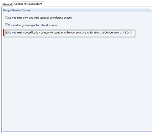
In the H - Roofs category, imposed loads have to be applied. These are usually the technician loads for construction and maintenance. Since there is no maintenance for snow, category H must not include both snow and imposed loads together. You can consider thi in the options for automatic combinations.

The automatic creation of combinations in RFEM and RSTAB with the "EN 1990 + EN 1991‑3; Cranes" option allows you to design crane runway beams as well as support loads on the rest of the structure.

In addition to the geometry and shape of a flat roof, you can also take into account the formation of an eaves area when generating the loading.
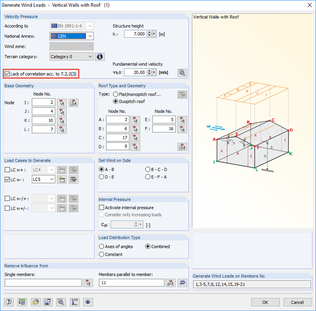
If the wind load for buildings or structures is to be determined by the simultaneous assumption of aerodynamic pressure and suction coefficients on the windward and leeward sides of the building, the correlation of the wind pressure on zones D and E of the wall surfaces may be taken into account.
![Structural System for Schöck Isokorb® Type K from [1]](/en/webimage/009555/2419353/01-en-png.png?mw=640&hash=c76563b459152b19c98197ea6ba342be89d9a5bc)
Heat loss due to external components without thermal decoupling of the internal components is enormous. For this reason, external structural components are thermally separated from the building envelope using a special built-in component. For the connection of a balcony slab with a reinforced concrete floor, Schöck Isokorb® or HALFEN HIT Insulated Connection can be used, for example. For the design of such built-in components, the respective technical approval must be taken into account. The following article shows an example of considering Schöck Isokorb® in the FEM calculation.