70 Results
View Results:
Sort by:

Moment frame design according to AISC 341-16 is now possible in the Steel Design add-on of RFEM 6. The seismic design result is categorized into two sections: member requirements and connection requirements. This article covers the required strength of the connection. An example comparison of the results between RFEM and the AISC Seismic Design Manual [2] is presented.

Creating a validation example for Computational Fluid Dynamics (CFD) is a critical step in ensuring the accuracy and reliability of simulation results. This process involves comparing the outcomes of CFD simulations with experimental or analytical data from real-world scenarios. The objective is to establish that the CFD model can faithfully replicate the physical phenomena it is intended to simulate. This guide outlines the essential steps in developing a validation example for CFD simulation, from selecting a suitable physical scenario to analyzing and comparing the results. By meticulously following these steps, engineers and researchers can enhance the credibility of their CFD models, paving the way for their effective application in diverse fields such as aerodynamics, aerospace, and environmental studies.

Plate girder is an economical choice for long spans construction. I-section steel plate girder typically has a deep web to maximize its shear capacity and flange separation, yet thin web to minimize the self-weight. Due to its large height-to-thickness (h/tw) ratio, transverse stiffeners may be required to stiffen the slender web.

The automatic surface reinforcement design process determines a surface reinforcement that covers the required amount of reinforcement.

In computational fluid dynamics (CFD), complex surfaces that are not completely solid can be modeled using porous or permeability media. In the actual world, examples of such things include windbreak fabric structures, wire meshes, perforated facades and claddings, louvers, tube banks (stacks of horizontal cylinders), and so on.

This article shows you how to define different types of member transverse stiffeners in RFEM 6 and RSTAB 9. It also shows you how to consider them in the design as well as the calculation of members with 7 degrees of freedom.

With the release of the structural analysis programs RFEM 6, RSTAB 9, RSECTION 1, and RWIND 2, Dlubal Software introduces a new generation of structural analysis programs. True to the motto "Structural analysis that is fun ...", the program provides users with universal tools with which they can meet all the requirements in structural engineering. Find out more about the latest developments at Dlubal Software in this article.

Steel connections in RFEM 6 are defined as an assembly of components. In the new Steel Joints add-on, universally applicable basic components (plates, welds, auxiliary planes) are available for entering complex connection situations. The methods with which connections can be defined are considered in two previous Knowledge Base articles: “A Novel Approach to Designing Steel Joints in RFEM 6" and “Defining Steel Joint Components Using the Library".

The new generation of RFEM software is an intuitive, powerful, and easy-to-handle 3D FEA program that meets all the latest demands in modeling, calculation, and structural design. The modern design concept, as well as the introduction of new features, make the program even more innovative and user-friendly. The main differences between RFEM 6 and its previous version, RFEM 5, are discussed in the following text.
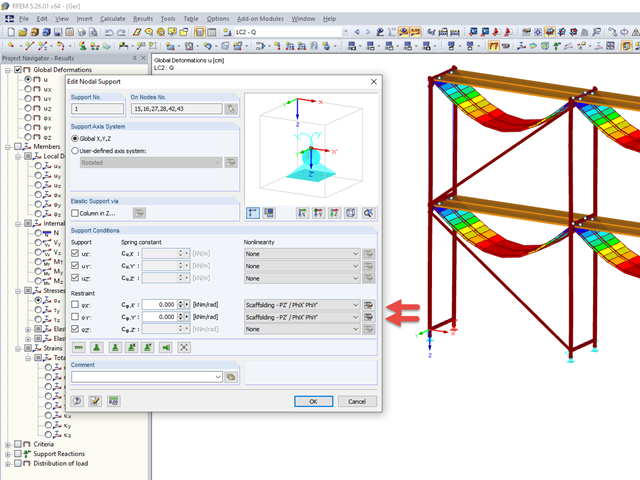
Temporary structures, such as scaffolding or props, are versatile structures that can be adapted very well to different geometric conditions.
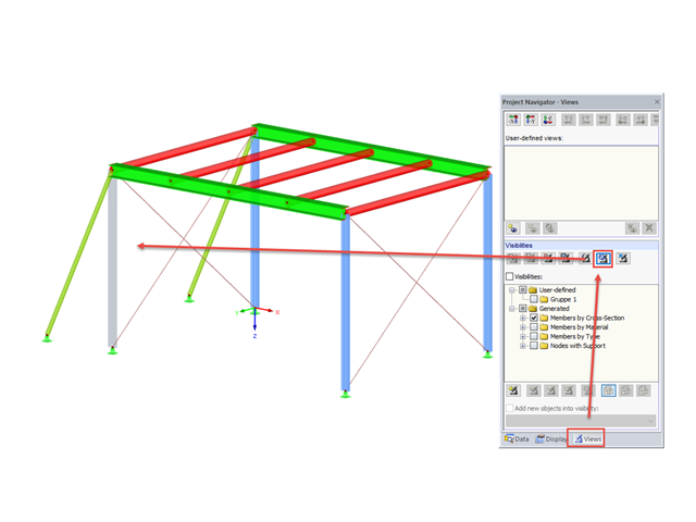
In RFEM and RSTAB, you can apply various visibilities in the Views project navigator.

In the age of BIM, data exchange between the various disciplines of structural engineering is becoming increasingly important. Since each software has its own specifications with regard to the description of cross-sections and materials, RFEM and RSTAB offer a conversion table (mapping file).
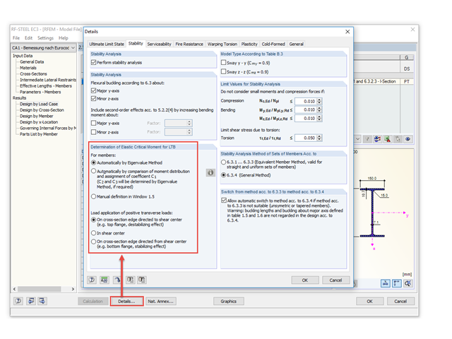
Occasionally, the question arises how to determine the correct load application point of the positive transverse loads in RF-/STEEL EC3 and RF-/STEEL AISC.

When calculating foundations according to EC 7 or EC 2, different foundation types or sizes are usually used in one object. However, boundary conditions like the soil parameters, the materials for foundations, concrete covers, and the load combinations selected for design remain the same for all foundations, as a rule.

For a quick overview of the cross‑sections used, you can show the members in color sorted by cross‑section. Use the right mouse button in the work window to select "Colors in Graphics According to" → "Cross -Sections" from the shortcut menu. In the current program versions, you can use a panel with an editable color scale for this.
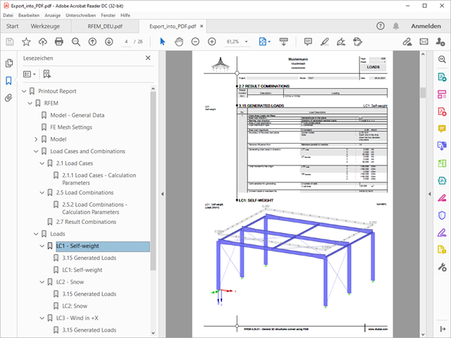
A PDF version of the printout report can be created in two ways. The most common way is to use a PDF printer that must be previously installed. The printer will be controlled like a real printer.
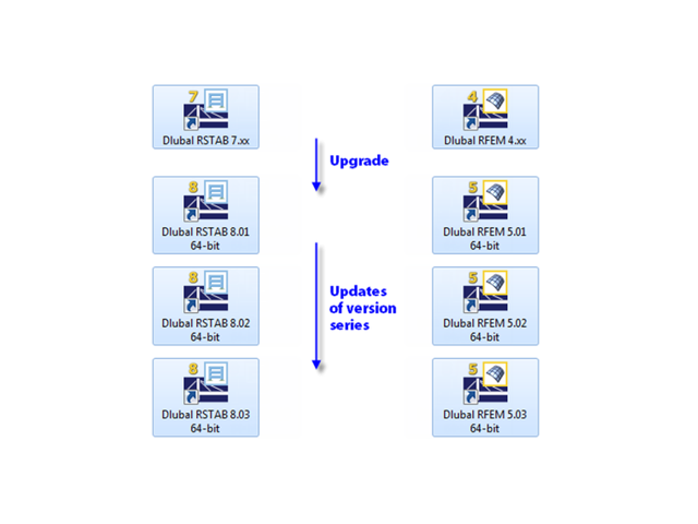
When updating within a version series (for example, RFEM 5.01.01 to 5.01.02), the old program files are removed and replaced by new ones. The project data, of course, remain unchanged. When updating to the next version series (for example, RFEM 5.02.01), the new version is installed in parallel. The program files are located in different directories, so the previous version is still available.
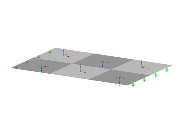
From time to time, it may happen that the axis systems of some surfaces in the model do not correspond to each other.

To cover the required transverse reinforcement, RF‑CONCRETE Members and CONCRETE determine the most cost-efficient transverse reinforcement as a reinforcement proposal in accordance with the predefined stirrup diameter.

Utilizing the RF-STEEL AISC add-on module, steel member design is possible according to the AISC 360-16 standard. The following article will compare the results between calculating lateral torsional buckling according to Chapter F and Eigenvalue Analysis.

The elastic deformations of a structural component due to a load are based on Hooke's law, which describes a linear stress-strain relation. They are reversible: After the relief, the component returns to its original shape. However, plastic deformations lead to irreversible deformations. The plastic strains are usually considerably larger than the elastic deformations. For plastic stresses of ductile materials such as steel, yielding effects occur where the increase in deformation is accompanied by hardening. They lead to permanent deformations - and in extreme cases to the destruction of the structural component.

The design of cold-rolled steel products is defined in EN 1993-1-3. Typical cross-section shapes are channel, C, Z, top hat, and sigma sections. These are cold-rolled steel products made of thin-walled sheet metal that has been cold-formed by roll-forming or bending methods. When designing the ultimate limit states, it is also necessary to ensure that local transverse forces do not lead to compression, crippling of the web, or local buckling in the web of the sections. These effects can be caused by local transverse forces by the flange into the web, as well as by support forces at the supported points. Section 6.1.7 of EN 1993-1-3 specifies in detail how to determine the resistance of the web Rw,Rd under local transverse forces.

In RF-DYNAM Pro - Equivalent Loads, the equivalent seismic loads can be calculated according to different standards. By calculating the equivalent loads for each eigenmode, it is not directly possible to obtain the transversal shear for each story to perform an analysis afterwards. The following example describes the option to calculate the transversal shear quickly and efficiently.
.png?mw=640&hash=5852c5c8a1cdb9f021a168d75c0a0466fb430ef7)
Lattice towers represent typical applications in steel construction. Examples of this special type of truss structure are antenna and overhead line towers, as well as columns for wind power stations, cable cars, and supporting frame constructions. The modeling can be done individually in RFEM and RSTAB by entering various tower elements. Furthermore, you can use different copy functions and parameterized input options. However, this procedure normally requires considerable effort. It is more convenient to model such structures using prefabricated catalog elements provided by the Block Manager. These elements are automatically stored in the database during program installation. Thus, you can use tower segments, platforms, antenna brackets, cable ducts, and so on as parameterized building blocks for generating diverse tower structures.
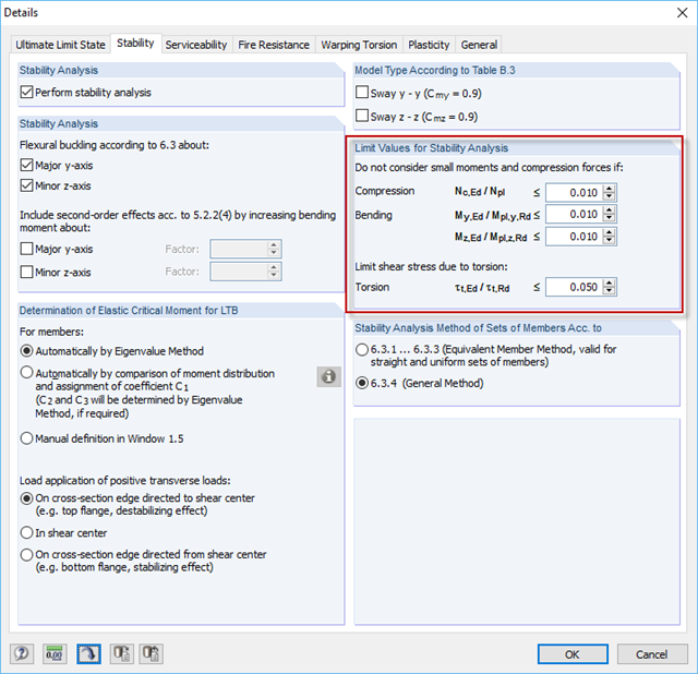
As of the program version X.11, the filter options of small compression forces or moments for stability analysis in RF‑/STEEL EC3 have been revised. The revision of these filter options in the "Stability" tab of the "Details" dialog box allows you to work in the module transparently, since they are now independent of the design.
![Formula Symbols for Connection Between Chords and Web (Source: [1])](/en/webimage/009346/2418256/01-en-3-png.png?mw=640&hash=7a1bc6e87da6f5aeb6d26a130c6ca3dfb6edb8a4)
In order to ensure the effects of panels, which should act as tensile or compression chords, it is necessary to connect them to the web in a shear-resistant manner. This connection is obtained in a similar way as the shear transfer in the joint between concreting sections by using the interaction between compressive struts and ties. In order to ensure the shear resistance, it must be verified that the compressive strut resistance is given and the tie force can be absorbed by the transverse reinforcement.

Composite beams in a three-dimensional analysis are usually connected with orthotropic plates. In that case, the longitudinal direction of the plate stiffness is defined by a main beam and the transverse direction by an orthotropic plate. The stiffness of the plate in the longitudinal direction is set almost to zero. This article explains the determination of stiffnesses in the orthotropic plate.
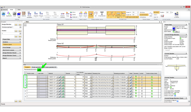
With program version RFEM 5.06, you can edit several tendons in the RF‑TENDON add‑on module simultaneously. To do this, it is necessary to select the corresponding tendons in the tendon arrangement table.
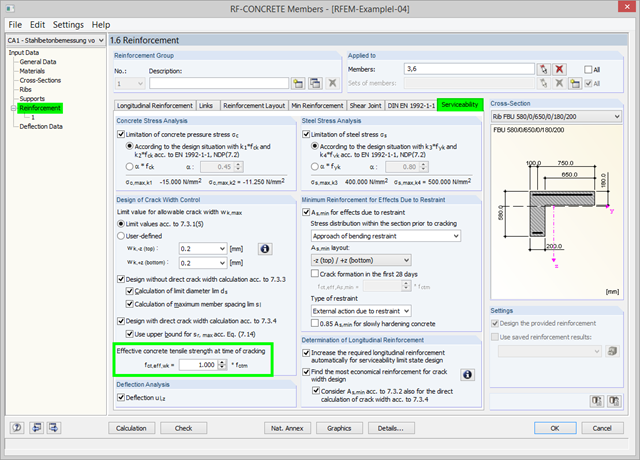
As of program version 5.06, you can use the option to adjust the effective concrete tensile strength fct,eff,wk at the time of cracking. At the start of the SLS design, the program checks whether the internal forces can cause cracks in the concrete. For this, the effective concrete tensile strength at the time of cracking is applied. You can adjust the strength via the factor. The calculation details display the adjusted value.
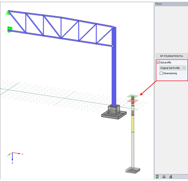
With version x.06.1103, the input of a soil profile was introduced in RF-/FOUNDATION Pro.