135 Results
View Results:
Sort by:

RWIND 2 and RFEM 6 can now be used to calculate wind loads from experimentally measured wind pressures on surfaces. Basically, two interpolation methods are available to distribute pressures measured in isolated points across the surfaces. The desired pressure distribution can be achieved using the appropriate method and parameter settings.

If you want to use a pure surface model, for example, when determining the internal forces and moments, but the structural component is still designed on the member model, you can take advantage of a result beam.

In RFEM 6, the results for the FE mesh nodes are determined using the finite element method. For the distribution of internal forces, deformations, and stresses to be continuous, these nodal values are smoothed through an interpolation process. This article will introduce and compare the different types of smoothing that you can use for this purpose.

Surfaces in building models can be of many different sizes and shapes. All surfaces can be considered in RFEM 6 because the program allows to define different materials and thicknesses as well as surfaces with different stiffness and geometry types. This article focuses on four of these surface types: rotated, trimmed, without thickness, and load transfer.

A new capability within RFEM 6 when designing concrete columns is being able to generate the moment interaction diagram according to the ACI 318-19 [1]. When designing reinforced concrete members, the moment interaction diagram is an essential tool. The moment interaction diagram represents the relationship between the bending moment and axial force at any given point along a reinforced member. Valuable information is shown visually like strength and how the concrete behaves under different loading conditions.

In computational fluid dynamics (CFD), complex surfaces that are not completely solid can be modeled using porous or permeability media. In the actual world, examples of such things include windbreak fabric structures, wire meshes, perforated facades and claddings, louvers, tube banks (stacks of horizontal cylinders), and so on.

Line releases are special objects in RFEM 6 that allow structural decoupling of objects connected to a line. They are mostly used to decouple two surfaces that are not rigidly connected or transferring only compressive forces at the common boundary line. By defining a line release, a new line is generated at the same place which transfers only the locked degrees of freedom. This article will show the definition of line releases in a practical example.
RWIND 2 is a program for generating wind loads based on CFD (Computational Fluid Dynamics). The wind flow numerical simulation is generated around any building, including irregular or unique geometry types, to determine the wind loads on surfaces and members. RWIND 2 can be integrated with RFEM/RSTAB for the structural analysis and design or as a stand-alone application.

In RFEM 6 it is possible to define multilayer surface structures with the help of the “Multilayer Surfaces” add-on. Hence, if you have activated the add-on in the model’s Base Data, it is possible to define layer structures of any material model. You can also combine material models of, for example, isotropic and orthotropic materials.

This article shows you how to create contacts between two or more parallel surfaces by controlling the transfer of forces between them.

This article will show you how to properly consider the connection between surfaces that touch each other on one line with the help of line hinges in RFEM 6.

In RFEM 6, it is possible to define line welds on lines between surfaces and calculate the weld stresses using the Stress-Strain Analysis add-on. This article will show you how to do it.
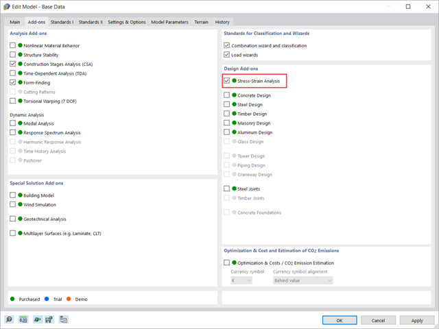
This article shows how to manage the input data for member and surface design configurations within the Stress-Strain Analysis add-on.

This article shows you the internal forces and displacements of a continuous beam calculated both with and without consideration of shear stiffness.

RWIND 2 is a program for generating wind loads based on CFD (Computational Fluid Dynamics). The wind flow numerical simulation is generated around any building, including irregular or unique geometry types, to determine the wind loads on surfaces and members. RWIND 2 can be integrated with RFEM/RSTAB for the structural analysis and design or as a stand-alone application.

In accordance with Sect. 6.6.3.1.1 and Clause 10.14.1.2 of ACI 318-19 and CSA A23.3-19, respectively, RFEM effectively takes into consideration concrete member and surface stiffness reduction for various element types. Available selection types include cracked and uncracked walls, flat plates and slabs, beams, and columns. The multiplier factors available within the program are taken directly from Table 6.6.3.1.1(a) and Table 10.14.1.2.

This article explains the use of surfaces with the Load Transfer stiffness type in RFEM 6. A practical example is also provided to demonstrate the application of self-weight, snow load, and wind load to a steel hall.

In order to create a surface model with failing supports close to reality, an option called "Failure if contact perpendicular to surfaces failed" is available in RFEM 5 for contact solids under "Contact Parallel to Surfaces".

In RFEM and RSTAB, there are various options to renumber the individual structural elements, such as nodes, lines, members, surfaces, or solids. Two options are available for renumbering: singly and automatically.

In RFEM and RSTAB, parametrization provides you with many options, especially for recurring structural elements. Within the parametrization tool, you can access the internal values of a model; for example, the values of a selected cross‑section. The following example shows how this can work.

In RFEM, it is possible to display the resultant of a section or release. This article explains which part of the sectional area is affected. The easiest way would be to refer the resultant to a cut face of the surface. However, since a section may run through several surfaces with different local coordinate systems, determination by means of a cut face is not possible.

In RFEM, you can display the contact properties between two surfaces by means of contact solids. Among other things, you should ensure that both contact surfaces of a contact solid have the same integrated objects. Therefore, when modeling the contact surfaces, we recommend using the copy function in order to create the second contact surface.

In RFEM, you can display the contact properties between two surfaces by means of contact solids.

You can make various settings in order to achieve a clearly‑arranged display of the result values. For example, some users may not want the white background in text bubbles. You can adjust the background in "Display Properties" using the Transparent and Background color option.

Inserting holes in surfaces is very easy due to the large selection of tools. In order to insert holes or drilling in solids, it is necessary to keep in mind that an opening at the beginning and the end of a continuous hole must be created, as well as a surface that separates the hole from the solids.
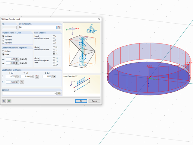
In RFEM, loads can be freely defined on surfaces. It is impossible, however, to define a variable loading on, for example, circular surfaces. However, you can still create this type of loading by using a free circular load.
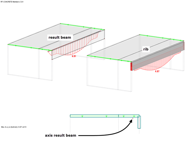
Although the design of downstand beams is usually carried out on a member model, a result beam can be used to perform the design on a model with only surfaces.
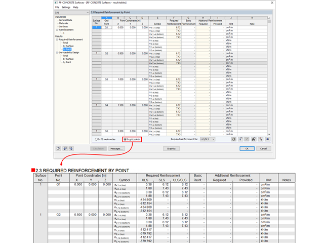
The results from RF‑CONCRETE Surfaces can be documented in tabular form in the printout report.

In RF-/STEEL EC3, you can optimize a cross-section automatically within the design. To do this, select the corresponding cross-section in Table 1.3 or define variable parameters for a welded cross-section.

For solids, there is another option for the FE mesh setting. You can arrange a layered FE mesh in addition to a holistic FE mesh refinement. For this option, you can perform a defined division of the solid with finite elements between two parallel surfaces. This option is particularly suitable for very large solid geometries with a low height.