132 Results
View Results:
Sort by:

Creating a validation example for Computational Fluid Dynamics (CFD) is a critical step in ensuring the accuracy and reliability of simulation results. This process involves comparing the outcomes of CFD simulations with experimental or analytical data from real-world scenarios. The objective is to establish that the CFD model can faithfully replicate the physical phenomena it is intended to simulate. This guide outlines the essential steps in developing a validation example for CFD simulation, from selecting a suitable physical scenario to analyzing and comparing the results. By meticulously following these steps, engineers and researchers can enhance the credibility of their CFD models, paving the way for their effective application in diverse fields such as aerodynamics, aerospace, and environmental studies.

The Geotechnical Analysis add-on provides RFEM with additional specific soil material models that are able to suitably represent complex soil material behavior. This technical article is an introduction to show how the stress-dependent stiffness of soil material models can be determined.

Compliance with building codes, such as Eurocode, is essential to ensure the safety, structural integrity, and sustainability of buildings and structures. Computational Fluid Dynamics (CFD) plays a vital role in this process by simulating fluid behavior, optimizing designs, and helping architects and engineers meet Eurocode requirements related to wind load analysis, natural ventilation, fire safety, and energy efficiency. By integrating CFD into the design process, professionals can create safer, more efficient, and compliant buildings that meet the highest standards of construction and design in Europe.

This article shows how to create cross-sections using DXF files.

Large-scale models are models which contain multiple dimensional scales and thus are demanding on computational power. This article will show you how to simplify and optimize the calculation of such models with respect to the desired results.

Custom sections are often required in cold-formed steel design. In RFEM 6, the custom section can be created using one of the “Thin-Walled” sections available in the library. For other sections that do not meet any of the 14 available cold-formed shapes, the sections can be created and imported from the standalone program, RSECTION. For general information on AISI steel design in RFEM 6, refer to the Knowledge Base article provided at the end of the page.

Steel connections in RFEM 6 can be created by simply entering predefined components in the Steel Joints add-on. The collection of these components is constantly being improved to make your work even easier even when modeling steel connections. In this article, the connection plate component is introduced as a component recently added to the add-on's library.

Surfaces in building models can be of many different sizes and shapes. All surfaces can be considered in RFEM 6 because the program allows to define different materials and thicknesses as well as surfaces with different stiffness and geometry types. This article focuses on four of these surface types: rotated, trimmed, without thickness, and load transfer.

The Nonlinear Material Behavior add-on enables the consideration of material nonlinearities in RFEM 6. This article provides an overview of the available nonlinear material models, which are available after activating the add-on in the model’s Base Data.

In this paper, a novel approach was developed to generate CFD models at the community-level by integrating building information modeling (BIM) and geographical information systems (GIS) to automate the generation of a high-resolution 3-D community model to be employed as an input for a digital wind tunnel using RWIND.

In RFEM 6 it is possible to define multilayer surface structures with the help of the “Multilayer Surfaces” add-on. Hence, if you have activated the add-on in the model’s Base Data, it is possible to define layer structures of any material model. You can also combine material models of, for example, isotropic and orthotropic materials.

This article shows you how to create contacts between two or more parallel surfaces by controlling the transfer of forces between them.
This article summarizes the advantages of working with parameterized models in RFEM 6 and RSTAB 9.
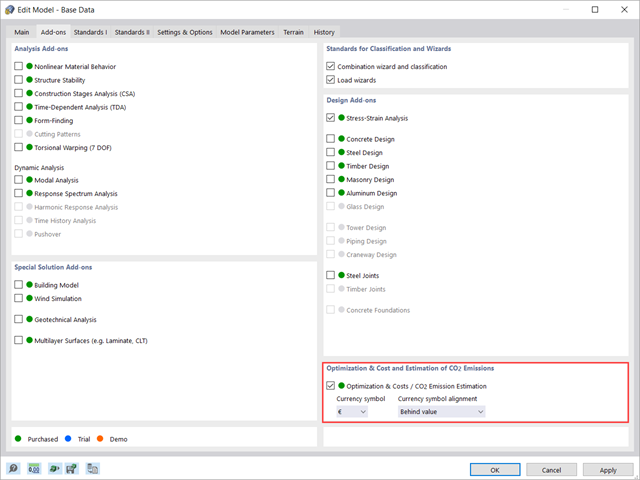
This article shows you how to use the add-on Optimization & Costs / CO2 Emission Estimation to estimate the model costs. Furthermore, it shows you how to optimize parameters based on minimum cost when working with parameterized models and blocks.

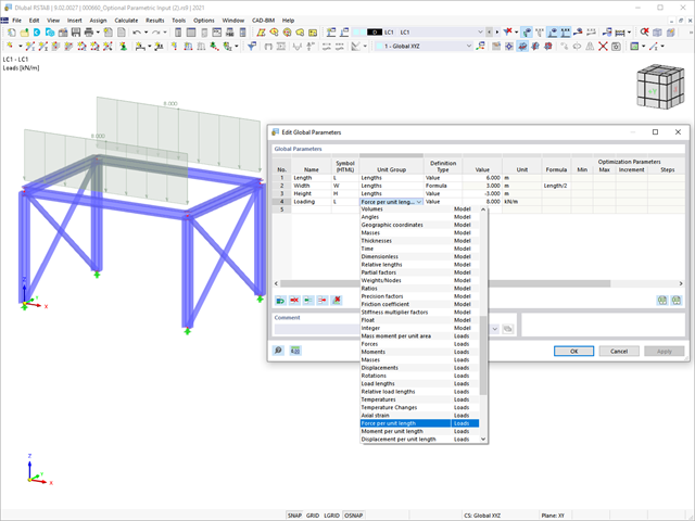
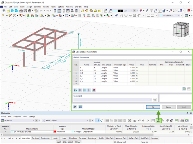
RFEM and RSTAB programs provide parameterized input as an advantageous product feature to create or adjust models by means of variables. This article will show you how to define global parameters and use them in formulas to determine numerical values.

The dynamic analysis in RFEM 6 and RSTAB 9 is divided into several add-ons. The Modal Analysis add-on is a prerequisite for all other dynamic add-ons, since it performs the natural vibration analysis for member, surface, and solid models.

You can model and analyze masonry structures in RFEM 6 with the Masonry Design add-on that employs the finite element method for the design. Complex masonry structures can be modeled, and static and dynamic analysis can be performed, given that a nonlinear material model is implemented in the program to display the load-bearing behavior of masonry and the different failure mechanisms. You can enter and model masonry structures directly in RFEM 6 and combine the masonry material model with all common RFEM add-ons. In other words, you can design entire building models in connection with masonry.

You can use the Steel Joints add-on in RFEM 6 to create and analyze steel connections using an FE model. You can control the modeling of the connections via a simple and familiar input of components. Steel joint components can be defined manually, or by using the available templates in the library. The former method is included in a previous Knowledge Base article titled “A Novel Approach to Designing Steel Joints in RFEM 6". This article will focus on the latter method; that is, it will show you how to define steel joint components using the available templates in the program’s library.

Structures in RFEM 6 can be saved as blocks and reused in other RFEM files. The advantage of dynamic blocks with respect to non-dynamic blocks is that they allow interactive modifications of the structural parameters as a result of modified input variables. One example is the possibility to add structural elements by changing only the number of bays as an input variable. This article will demonstrate the aforementioned possibility for dynamic blocks that are created by scripting.
In addition to the predefined models available as blocks in Dlubal Center | Blocks, it is possible to create new blocks and save them in the manner discussed in the Knowledge Base article "Saving Models as Blocks in RFEM 6".

In RFEM 6 it is possible to save selected objects (as well as whole structures) as blocks and reuse them in other models. Three types of blocks can be distinguished: non-parameterized, parameterized, and dynamic blocks (via JavaScript). This article will focus on the first block type (non-parameterized).

The calculation of complex structures by means of finite element analysis software is generally performed on the entire model. However, the construction of such structures is a process carried out in multiple stages where the final state of the building is achieved by combining the separate structural parts. To avoid errors in the calculation of overall models, the influence of the construction process must be considered. In RFEM 6, this is possible using the Construction Stages Analysis (CSA) add-on.

RFEM 6 includes the Form-Finding add-on to determine the equilibrium shapes of surface models subjected to tension and members subjected to axial forces. Activate this add-on in the model's Base Data and use it to find the geometric position in which the prestress of lightweight structures is in equilibrium with the existing boundary conditions.

Building Model is one of the special solution add-ons in RFEM 6. It is an advantageous tool for modeling, with which building stories can be created and manipulated easily. Building Model can be activated at the beginning of the modeling process and afterwards.
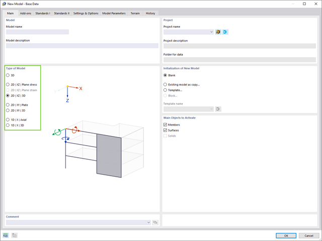
Structures are three-dimensional in reality; however, they can be simplified and analyzed as 2D or 1D models. The model type has a crucial influence on how the structural components are stressed, and it should be defined prior to modeling and calculation.

In order to create a surface model with failing supports close to reality, an option called "Failure if contact perpendicular to surfaces failed" is available in RFEM 5 for contact solids under "Contact Parallel to Surfaces".
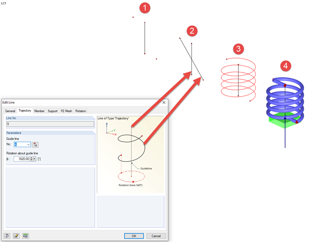
In RFEM, you can create screw lines using the "Trajectory" type line. To do this, you need a center line/guide line around which the line can be modeled, as well as a start and end point. Then, you can create a "Trajectory" type line between the start and end points; this initially appears as a straight line.
In RFEM and RSTAB, you can simulate extensive complex models from different materials in one computing environment.

In RFEM 5 as well as RSTAB 8 in RF-/FOUNDATION Pro, you can save the foundation dimensions for all five foundation types as foundation templates in a user-defined database and use them later in other models.

In RF-/STEEL EC3, sets of members are calculated according to the General Method (EN 1993-1-1, Cl. 6.3.4) together with the stability analysis. To do this, it is necessary to determine the correct support conditions for the equivalent structure with four degrees of freedom. In most 3D models today, you can quickly lose track of the location of a set of members in the system.