39 Results
View Results:
Sort by:

As you may already know, RFEM 6 offers you the possibility to consider material nonlinearities. This article explains how to determine internal forces in slabs modeled with nonlinear material.

You can use the stand-alone program RSECTION to determine the section properties for any thin-walled and massive cross-sections, as well as to perform a stress analysis. The previous Knowledge Base article titled "Graphical/Tabular Creation of User-defined Cross-sections in RSECTION 1" discussed the basis of defining cross-sections in the program. This article, on the other hand, is a summary of how to determine the section properties and perform a stress analysis.

RSECTION 1 is a stand-alone program for determining section properties for both thin-walled and massive cross-sections, as well as for performing a stress analysis. In addition, the program can be connected to both RFEM and RSTAB: sections from RSECTION are available in the RFEM/RSTAB libraries, and internal forces from RFEM/RSTAB can be imported into RSECTION.
The tools arrangement in the workplace can make your work fast and efficient.

Foundations including dimensions can be saved as a template in a user-defined database.

In RFEM 5 as well as RSTAB 8 in RF-/FOUNDATION Pro, you can save the foundation dimensions for all five foundation types as foundation templates in a user-defined database and use them later in other models.
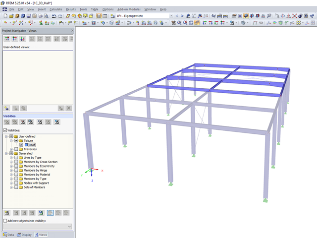
In RFEM and RSTAB, you can apply various visibilities in the Views project navigator.

To work even more efficiently, RF‑GLASS allows you to create and save different, user‑defined layer structures that can be reimported later or loaded in another project.
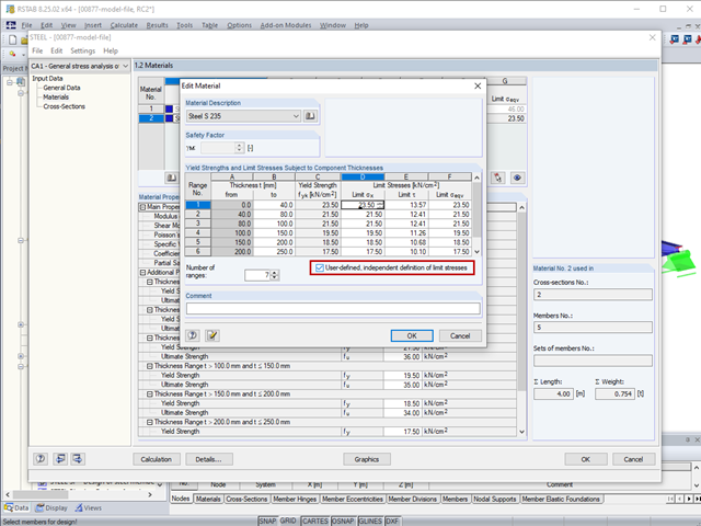
The limit stresses in RF‑/STEEL can be user-defined for each thickness range.

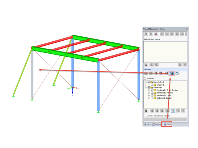
RFEM and RSTAB offer many display options in the Display Navigator. They can be completely different, depending on their function. You often have to click several times to make certain changes. If you want to optimize your work, you can create user‑defined views. In these views, you can save all specified settings. The following example illustrates this principle.
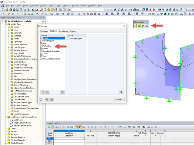
An individual user‑defined workspace can increase your productivity and make your daily work easier. This is why many users take the opportunity to adjust the toolbars in RFEM and RSTAB and to create their own toolbars containing the most frequently used commands.
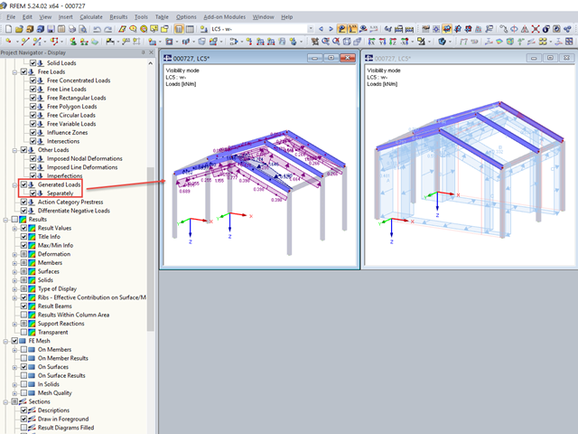
If, after defining the generated loads belonging together, you switch to the visibility mode, the loads are also shown on the hidden structural elements.
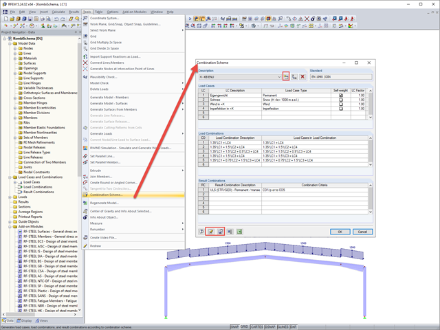
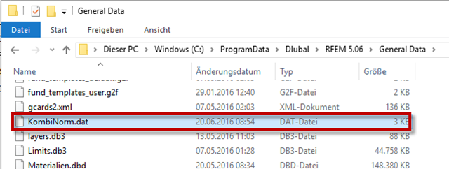
In RFEM and RSTAB, you can define a user-defined combination scheme. This can be helpful if a desired combination scheme cannot be created from a standard. In such cases, you can export the created load cases to Excel, create the scheme there, then import them to RFEM or RSTAB.

In RFEM, RSTAB, and SHAPE-THIN, you can create user-defined print templates ("Printout Report Template") and printout headers ("Report Headers"). These templates can also be transferred to other computers and used there.
User-defined visibilities facilitate program handling. Once created, any model groups can be quickly hidden or shown. This facilitates, among other things, the analysis of the results in larger 3D structures, as well as the creation of the report. When changing the geometry, the existing visibilities may have to be updated.
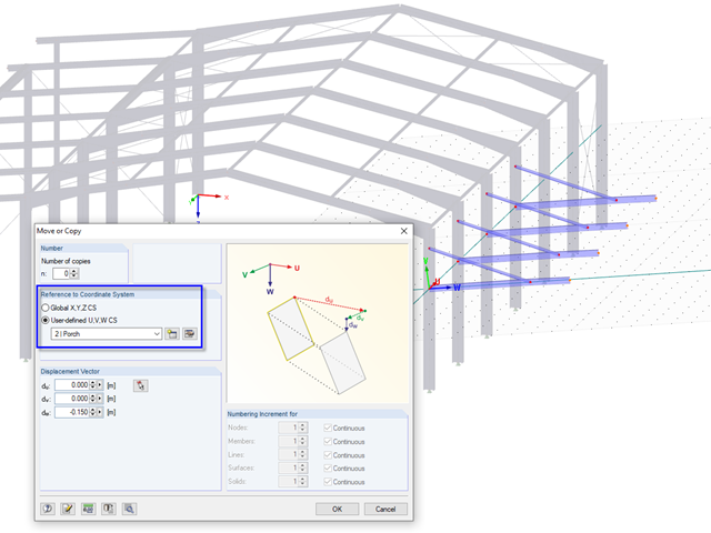
In RFEM and RSTAB, it is possible to move or copy models or parts of the model in a user-defined coordinate system. To use this option, a user-defined coordinate system must be available, of course.
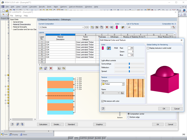
To better distinguish between the different layer compositions (for example, for walls and ceilings), you can assign user‑defined colors and textures to each composition.
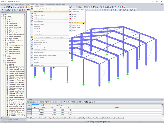
In RFEM 5 and RSTAB 8, you can now create a work plane by simply selecting three points. It is no longer necessary to create a user-defined coordinate system.
This article describes how to create a user-defined antenna bracket to be used in RF-/TOWER Equipment.
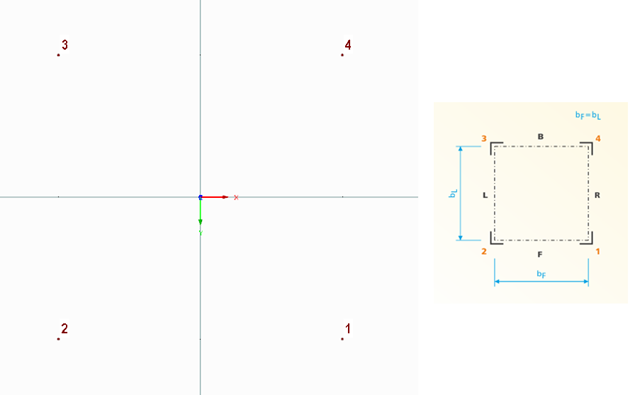
The following technical article describes the creation of a user-defined platform for use on a four-sided tower in the RF-/TOWER add-on modules. First, start with an empty model of the 3D type and define four nodes. The numbering and position of these nodes are very important here.

When designing steel columns or steel beams, it is usually necessary to carry out cross-section design and stability analysis. While the cross-section design can usually be performed without giving further details, the stability analysis requires further user-defined entries. To a certain extent, the member is cut out of the structure; therefore, the support conditions have to be specified. This is particularly important when determining the ideal elastic critical moment Mcr. Furthermore, it is necessary to define the correct effective lengths Lcr. These are required for the internal calculation of slenderness ratios.
![[Edit Parameters] Button in Table Toolbar](/en/webimage/009362/2418341/01-en-png.png?mw=640&hash=c76563b459152b19c98197ea6ba342be89d9a5bc)
The SHAPE‑THIN stand-alone program determines the characteristic values and stresses of any thin‑walled cross‑sections. Graphic tools and features allow for modeling complex cross‑section shapes. In addition to the graphical input, it is also possible to enter the data in tables. As an alternative, you can import a DXF file and use it as a basis for further modelling. Also, each cross-section can be entered using the cross-section library of Dlubal Software and combined as a part with the user-defined elements.
RFEM and RSTAB provide the option to create national annexes with user-defined partial safety factors and combination coefficients. They can also be transferred to other computers.
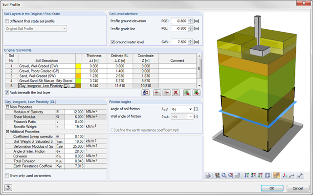
As of program version x.06.1103, you can enter a soil profile in RF‑/FOUNDATION Pro. This gives you the advantage of setting several soil layers with different soil parameters above and below the foundation base. To enter the soil layers, there is a library with various soil types that can also be extended with user‑defined soils. The user-defined soil profile is shown in an interactive information graphic. Any change (for example, a soil thickness modification) is reflected in the graphic immediately.
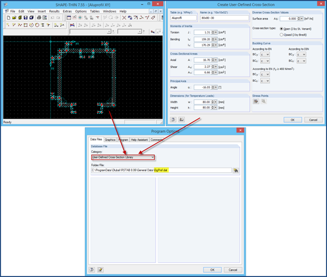
There are two ways of adding cross‑sections that are not included in the extensive cross‑section library: 1. You can create the cross‑section in the cross‑section programs SHAPE‑THIN or SHAPE‑MASSIVE and import it to RFEM/RSTAB. 2. If the cross‑section properties are provided by the manufacturer, you can add it to the RFEM/RSTAB cross‑section library using the option "New User‑Defined Cross‑Section".
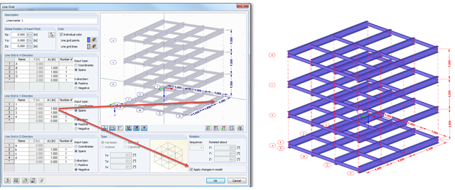
Arranging a model into an axis can provide better visibility, and in addition, the line grid can allow you to apply changes quickly in the model.
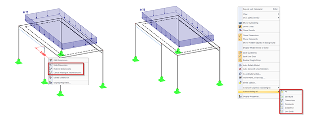
In addition to the options of Project Navigator - Display, you can modify the visibility of structures (members, surfaces, and so on) and guide objects (dimensions, comments, guidelines, and so on) in the menu and toolbar using the shortcut menus.
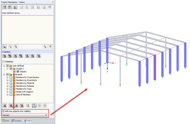
If new objects are created in an existing visibility, they are hidden immediately, since they do not comply with the particular visibility. However, if you want to display the new objects immediately in an existing visibility, for example when creating a new member, simply select the "Add new objects to visibility" check box.
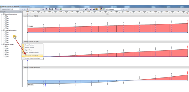
In RFEM and RSTAB, the check boxes for deformation in result diagrams are selected by default. To avoid creating a new user-defined result display every time, you can save the selection of check boxes displayed on the left.
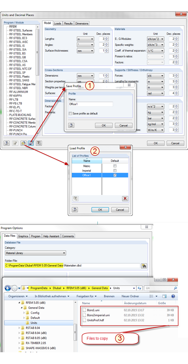
In RFEM and RSTAB, there are two predefined unit profiles available by default. These profiles cover the metric and the imperial systems of measurement. You can individually adjust the units predefined by Dlubal Software, including the decimal places used. To avoid losing the changes you have made, you can save a new profile for the units (see Item [1] in the picture). The stored profile can be loaded again (see Item [2] in the picture) or transferred from PC to PC. To do this, simply copy the content of the "Units" folder in the RFEM or RSTAB file directory from one PC to another (see Item [3] in the picture). In this way, you can achieve an office standard regarding the units used in all your workplaces.