24 Wyniki
Wyświetl wyniki:
Sortuj według:
W inżynierii konstrukcyjnej przewidywanie wpływu turbulentnego przepływu wiatru na konstrukcje ma kluczowe znaczenie dla bezpieczeństwa i wydajności. Modelowanie turbulencji w Computational Fluid Dynamics (CFD) pomaga w symulacji tych interakcji. Inżynierowie muszą wybrać praktyczny model turbulencji, równoważąc wydajność, dokładność i możliwości zastosowania. Typowe modele to uśredniony Navier-Stokes (RANS), niestabilny uśredniony Navier-Stokes (URANS) oraz Delayed Detached Eddy Simulation (DDES). Program RANS jest niezawodnym i ekonomicznym rozwiązaniem w przypadku stałych przepływów, URANS rejestruje zależne od czasu zjawiska dla średnich niestateczności, a DDES, hybryda RANS i symulacji dużych wirów (LES), rozwiązuje złożone struktury turbulentne. Zrozumienie mocnych stron i ograniczeń każdego modelu pomoże inżynierom wybrać najlepsze podejście do swoich potrzeb.
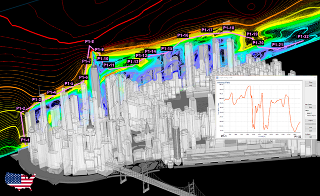
Stworzenie przykładu walidacyjnego dla obliczeniowej mechaniki płynów (CFD) jest kluczowym krokiem w zapewnieniu dokładności i wiarygodności wyników symulacji. This process involves comparing the outcomes of CFD simulations with experimental or analytical data from real-world scenarios. The objective is to establish that the CFD model can faithfully replicate the physical phenomena it is intended to simulate.
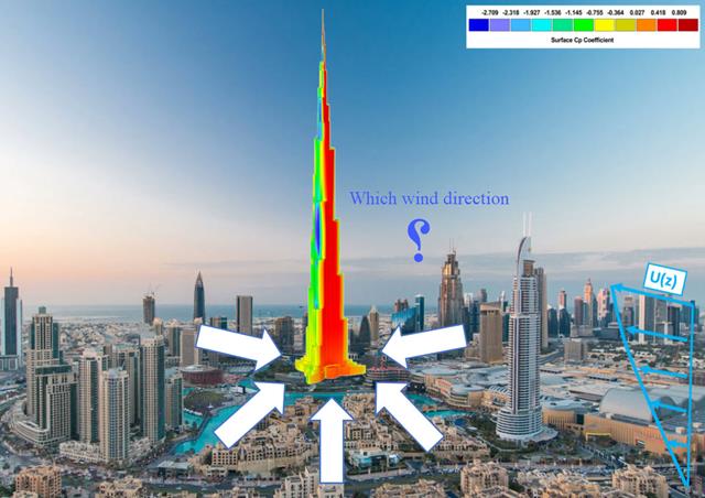
Kierunek wiatru odgrywa kluczową rolę w kształtowaniu wyników symulacji komputerowej mechaniki płynów (CFD) oraz w projektowaniu konstrukcyjnym budynków i infrastruktury. Jest to decydujący czynnik w ocenie interakcji sił wiatru z konstrukcjami, wpływających na rozkład ciśnienia wiatru, a w konsekwencji na reakcje konstrukcji.
Zgodność z przepisami budowlanymi, takimi jak Eurokod, jest niezbędna dla zapewnienia bezpieczeństwa, integralności konstrukcji i trwałości budynków i konstrukcji. Obliczeniowa mechanika płynów (CFD) odgrywa istotną rolę w tym procesie, symulując zachowanie płynów, optymalizując projekty i pomagając architektom i inżynierom w spełnieniu wymagań Eurokodu związanych z analizą obciążenia wiatrem, wentylacją naturalną, bezpieczeństwem pożarowym i efektywnością energetyczną. Integrując CFD z procesem projektowania, profesjonaliści mogą tworzyć bezpieczniejsze, wydajniejsze i zgodne z przepisami budynki, które spełniają najwyższe standardy konstrukcyjne i projektowe w Europie.
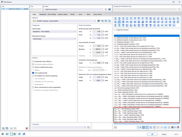
Aby umożliwić ocenę wpływu lokalnych zjawisk stateczności smukłych elementów, w programach RFEM 6 i RSTAB 9 można przeprowadzić liniową analizę obciążenia krytycznego na poziomie przekroju. Poniższy artykuł poświęcony jest podstawom obliczeń i interpretacji wyników.
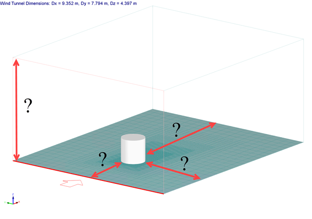
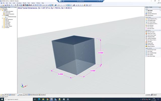
Rozmiar domeny obliczeniowej (rozmiar tunelu aerodynamicznego) jest ważnym aspektem symulacji wiatru, który ma znaczący wpływ na dokładność, a także na koszt symulacji CFD.

Wymiarowanie prętów stalowych formowanych na zimno zgodnie z AISI S100-16 jest teraz dostępne w programie RFEM 6. Design can be accessed by selecting “AISC 360” as the standard in the Steel Design add-on. “AISI S100” is then automatically selected for the cold-formed design (Image 01).

Osłony przeciwwiatrowe to specjalne konstrukcje tekstylne, które mają za zadanie chronić środowisko przed szkodliwymi cząsteczkami chemicznymi, jak również ograniczać erozję wietrzną, przyczyniając się do ochrony cennych zasobów. RFEM i RWIND są używane do analizy konstrukcji wiatrowej dla jednostronnej interakcji płyn-konstrukcja (FSI).
W tym artykule pokazano, jak wymiarować osłony przeciwwiatrowe przy użyciu programów RFEM i RWIND.
W tym artykule pokazano, jak wymiarować osłony przeciwwiatrowe przy użyciu programów RFEM i RWIND.

Rozszerzenie Projektowanie konstrukcji aluminiowych dla RFEM 6 wymiaruje pręty aluminiowe ze względu na stan graniczny nośności i użytkowalności zgodnie z Eurokodem 9. Ponadto możliwe jest wymiarowanie zgodnie z ADM 2020 (norma amerykańska).

Sprawdzenie stateczności dla wymiarowania prętów zastępczych zgodnie z EN 1993-1-1, AISC 360, CSA S16 i innymi normami międzynarodowymi wymaga uwzględnienia długości obliczeniowej (tj. efektywnej długości prętów). W programie RFEM 6 długość efektywną można określić ręcznie, przypisując podpory węzłowe i współczynniki długości efektywnej lub, z drugiej strony, poprzez import z analizy stateczności. Obie opcje zostaną przedstawione w tym artykule poprzez określenie efektywnej długości słupa obramowanego na rysunku 1.

Nowa generacja oprogramowania RFEM umożliwia przeprowadzanie obliczeń stateczności zbieżnych prętów drewnianych zgodnie z metodą prętów zastępczych. Zgodnie z tą metodą obliczenia można przeprowadzić, jeżeli spełnione są wytyczne normy DIN 1052, sekcja E8.4.2 dla zmiennych przekrojów. W różnych publikacjach technicznych metoda ta jest również stosowana w przypadku Eurokodu 5. W tym artykule pokazano, jak zastosować metodę prętów zastępczych dla belki dachowej o zbieżnej wysokości.
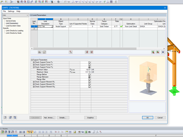
Mit dem Modul LIMITS ist es möglich die Tragfähigkeit von Stäben, Stabenden, Knoten, Knotenlagern und Flächen (nur RFEM) anhand einer definierten Grenztragfähigkeit zu vergleichen. Des Weiteren können Knotenverschiebungen sowie Querschnittsabmessungen kontrolliert werden. In diesem Beispiel sollen Stützenfüße eines Carports mit den vom Hersteller angegebenen, maximal zulässigen, Kräften verglichen werden.
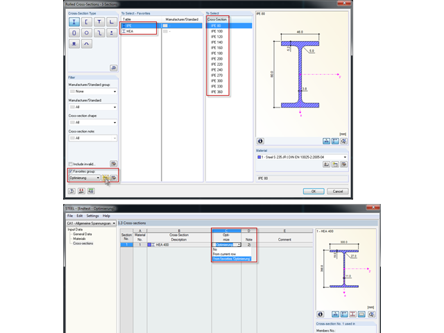
Bei der Querschnittsoptimierung in den Zusatzmodulen können auch beliebig definierte Querschnitts-Favoritenlisten ausgewählt werden - zusätzlich zu den Profilen aus der gleichen Profilreihe wie das ursprüngliche Profil.
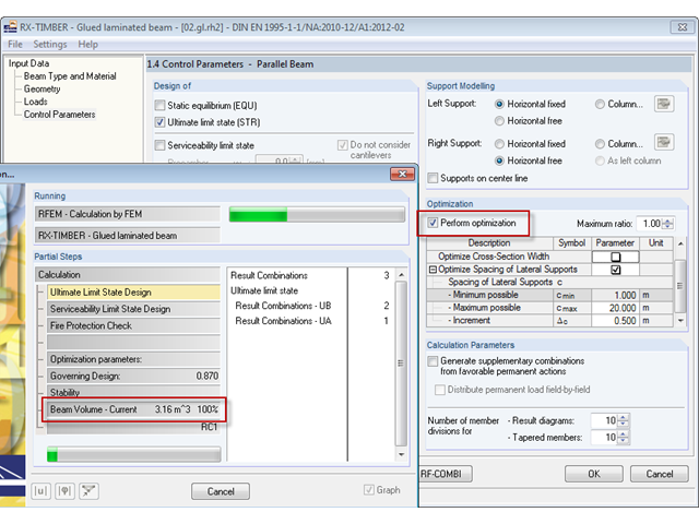
Im Programm RX-HOLZ kann optional eine Optimierung der Kippaussteifung erfolgen. Bei dieser Selektion wird iterativ die minimal notwendige Länge der Kippaussteifungen ermittelt.
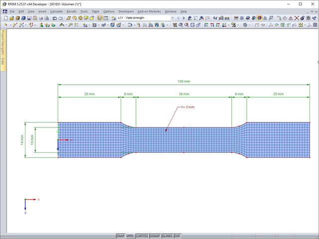
Deformacje sprężyste elementu konstrukcyjnego pod wpływem obciążenia są oparte na prawie Hooke'a, opisującym liniową zależność naprężenie-odkształcenie. Są one odwracalne: po odciążeniu element powraca do swojego pierwotnego kształtu. Jednakże deformacje plastyczne są nieodwracalne i zazwyczaj znacznie większe niż odkształcenia sprężyste. W przypadku naprężeń plastycznych materiałów ciągliwych, takich jak stal, efekty plastyczności występują w miejscach, w których wzrostowi odkształceń towarzyszy zjawisko lokalnego wzmocnienia. Prowadzi to do powstania trwałych deformacji, a w ekstremalnych przypadkach do zniszczenia elementu konstrukcyjnego.
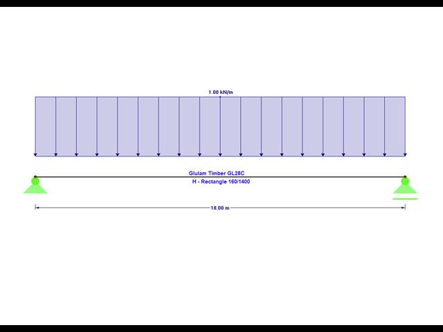
Artykuł Wyboczenie giętno-skrętne w konstrukcji drewnianej | Teoria wyjaśnia teoretyczne podstawy analitycznego określania momentu krytycznego M crit lub krytycznego naprężenia zginającego σcrit dla wyboczenia giętno-skrętnego belki zginanej. W poniższym artykule przedstawiono przykłady obliczeniowe, których celem jest weryfikacja wyników analizy wartości własnych względem wyników analitycznych.
.png?mw=640&hash=bfebd5ea2d4f77a817fa987424a23a799b3fe711)
W przypadku smukłych belek zginających o dużym stosunku h/w, obciążonych w kierunku słabej osi bezwładności, występują problemy ze statecznością. Wynika to z ugięcia pasu ściskanego.
Bei Kranbahnen mit großen Stützweiten ist nicht selten die Horizontallast aus Schräglauf bemessungsrelevant. In diesem Beitrag sollen die Entstehung dieser Kräfte und die richtige Eingabe in KRANBAHN beschrieben werden. Es wird hierbei auf die praktische Ausführung und den theoretischen Hintergrund eingegangen.
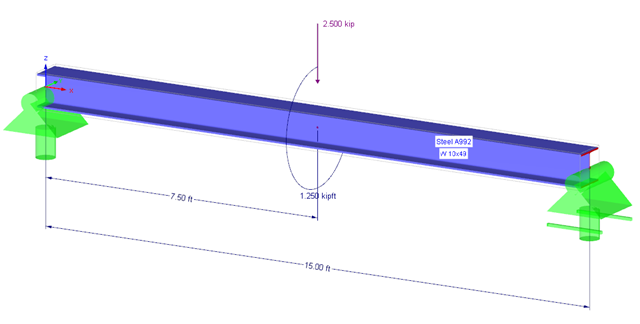
Anhand eines Verifikationsbeispiels soll die Bemessung eines torsionsbeanspruchten Trägers nach AISC Design Guide 9 gezeigt werden. Die Bemessung erfolgt mit dem Zusatzmodul RF-STAHL AISC und der Modulerweiterung RF-STAHL Wölbkrafttorsion mit sieben Freiheitsgraden.
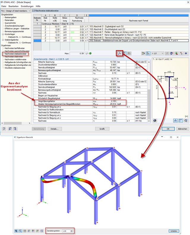
Po przeprowadzeniu analizy w module RF-/STEEL AISC, postacie drgań dla zbiorów prętów można wyświetlić graficznie w osobnym oknie. Select the relevant set of members in the result window and click the [Mode Shapes] button.
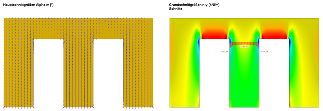
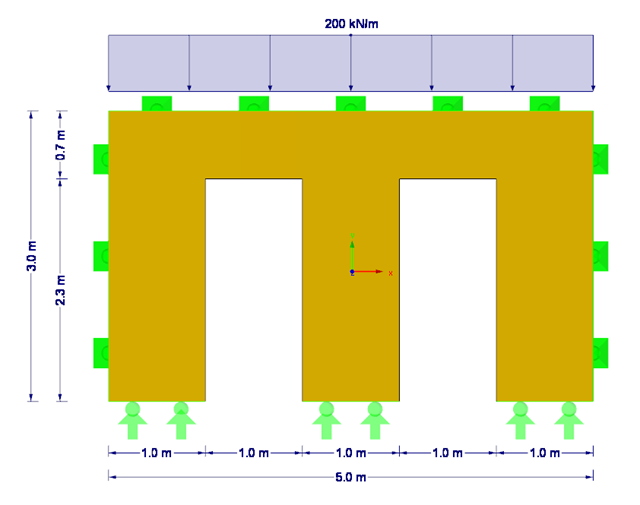
W tym artykule opisano, jako alternatywę dla metody prętów zastępczych, wyznaczyć siły wewnętrzne ściany podatnej na wyboczenie zgodnie z analizą drugiego rzędu z uwzględnieniem imperfekcji, a następnie przeprowadzić wymiarowanie przekroju na zginanie i ściskanie.
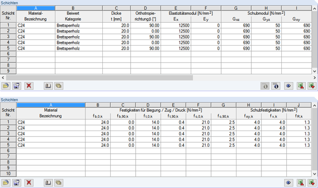
Poniższy artykuł opisuje wymiarowanie ściany z drewna klejonego krzyżowo, podatnej na wyboczenie, opisanej w pierwszej części tej serii artykułów, z wykorzystaniem metody prętów zastępczych, zgodnie z [1] sekcja 6.3.2. Analiza wyboczenia zostanie przeprowadzona jako analiza naprężeń ściskających ze zmniejszoną wytrzymałością na ściskanie. W tym celu określany jest współczynnik niestateczności kc, zależny przede wszystkim od smukłości elementu i typu podpory.
W module dodatkowym RF-LAMINATE można wymiarować elementy konstrukcyjne wykonane z drewna klejonego krzyżowo. Since the design is a pure elastic stress analysis, it is necessary to additionally consider the stability issues (flexural buckling and lateral-torsional buckling).
![Belka rozwidlona z rozproszonym obciążeniem (Źródło: [3])](/pl/webimage/009690/467522/01-de-png.png?mw=640&hash=52805a227240ecddbd69b1d113348bf2749c3f9e)
Belki z drewna klejonego o dużej rozpiętości są zazwyczaj podparte na słupie żelbetowym z ograniczeniami skrętnymi.