26 Wyniki
Wyświetl wyniki:
Sortuj według:

Obliczanie ramy momentowej zgodnie z AISC 341-16 jest teraz możliwe w rozszerzeniu Projektowanie konstrukcji stalowych dla programu RFEM 6. Wynik obliczeń sejsmicznych jest podzielony na dwie sekcje: wymagania dotyczące prętów i połączeń. W tym artykule omówiono wymaganą wytrzymałość połączenia. Przedstawiono przykładowe porównanie wyników pomiędzy RFEM a AISC Seismic Design Manual.

W rozszerzeniu Projektowanie konstrukcji stalowych dla programu RFEM 6 dostępne są trzy typy ram sprężystych (zwykłe, pośrednie i specjalne). Wyniki obliczeń sejsmicznych zgodnie z AISC 341-22 są podzielone na dwie sekcje: wymagania dotyczące prętów i połączeń.

W rozszerzeniu Projektowanie konstrukcji stalowych dla programu RFEM 6 dostępne są trzy typy ram sprężystych (zwykłe, pośrednie i specjalne). Wyniki obliczeń sejsmicznych zgodnie z AISC 341-16 są podzielone na dwie sekcje: wymagania dotyczące prętów i połączeń.

Rozszerzenie Projektowanie konstrukcji stalowych w RFEM 6 oferuje teraz możliwość przeprowadzania obliczeń sejsmicznych zgodnie z AISC 341-16 i AISC 341-22. Obecnie dostępnych jest pięć typów systemów sejsmicznych (SFRS).
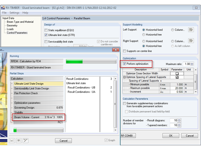
Im Programm RX-HOLZ kann optional eine Optimierung der Kippaussteifung erfolgen. Bei dieser Selektion wird iterativ die minimal notwendige Länge der Kippaussteifungen ermittelt.
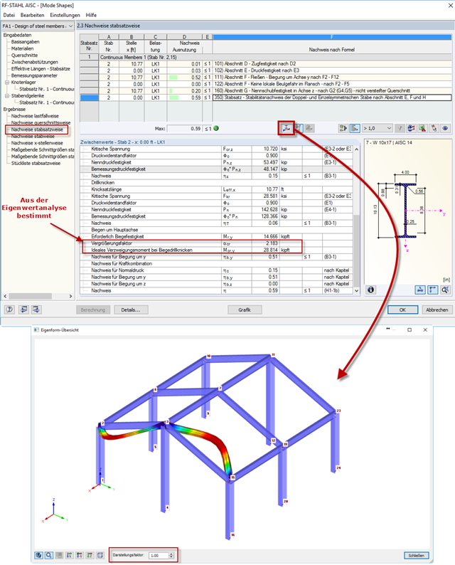
Po przeprowadzeniu analizy w module RF-/STEEL AISC, postacie drgań dla zbiorów prętów można wyświetlić graficznie w osobnym oknie. Select the relevant set of members in the result window and click the [Mode Shapes] button.
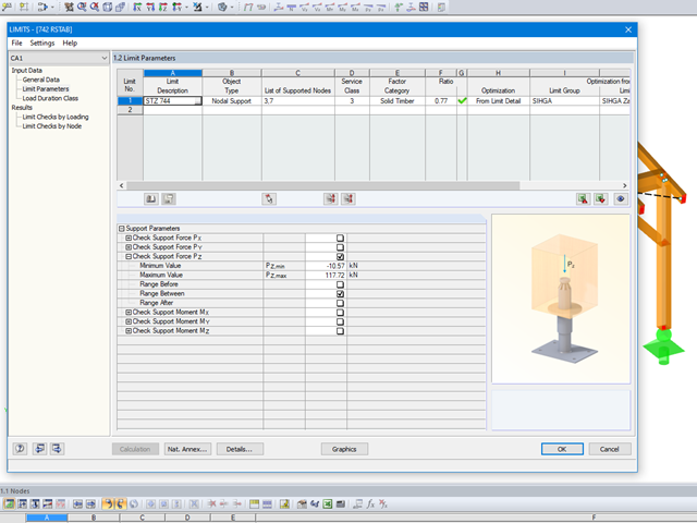
Mit dem Modul LIMITS ist es möglich die Tragfähigkeit von Stäben, Stabenden, Knoten, Knotenlagern und Flächen (nur RFEM) anhand einer definierten Grenztragfähigkeit zu vergleichen. Des Weiteren können Knotenverschiebungen sowie Querschnittsabmessungen kontrolliert werden. In diesem Beispiel sollen Stützenfüße eines Carports mit den vom Hersteller angegebenen, maximal zulässigen, Kräften verglichen werden.

Obliczenia zwykłej ramy stężonej koncentrycznie (OCBF) oraz SCBF (specjalnej konstrukcji szkieletowej stężonej koncentrycznie) można przeprowadzić w rozszerzeniu Projektowanie konstrukcji stalowych dla programu RFEM 6. Wyniki obliczeń sejsmicznych zgodnie z AISC 341-16 i 341-22 są podzielone na dwie sekcje: Wymagania dotyczące prętów i połączeń.

Wymiarowanie prętów stalowych formowanych na zimno zgodnie z AISI S100-16 jest teraz dostępne w programie RFEM 6. Design can be accessed by selecting “AISC 360” as the standard in the Steel Design add-on. “AISI S100” is then automatically selected for the cold-formed design (Image 01).
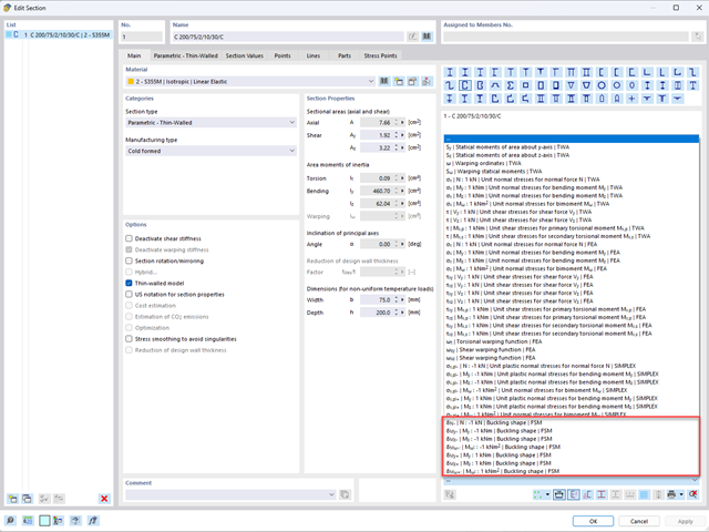
Aby umożliwić ocenę wpływu lokalnych zjawisk stateczności smukłych elementów, w programach RFEM 6 i RSTAB 9 można przeprowadzić liniową analizę obciążenia krytycznego na poziomie przekroju. Poniższy artykuł poświęcony jest podstawom obliczeń i interpretacji wyników.
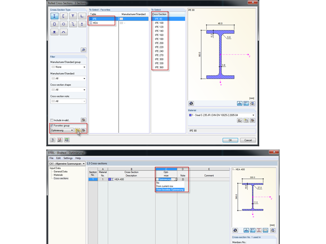
Bei der Querschnittsoptimierung in den Zusatzmodulen können auch beliebig definierte Querschnitts-Favoritenlisten ausgewählt werden - zusätzlich zu den Profilen aus der gleichen Profilreihe wie das ursprüngliche Profil.

Nowa generacja oprogramowania RFEM umożliwia przeprowadzanie obliczeń stateczności zbieżnych prętów drewnianych zgodnie z metodą prętów zastępczych. Zgodnie z tą metodą obliczenia można przeprowadzić, jeżeli spełnione są wytyczne normy DIN 1052, sekcja E8.4.2 dla zmiennych przekrojów. W różnych publikacjach technicznych metoda ta jest również stosowana w przypadku Eurokodu 5. W tym artykule pokazano, jak zastosować metodę prętów zastępczych dla belki dachowej o zbieżnej wysokości.
W tym artykule opisano, jako alternatywę dla metody prętów zastępczych, wyznaczyć siły wewnętrzne ściany podatnej na wyboczenie zgodnie z analizą drugiego rzędu z uwzględnieniem imperfekcji, a następnie przeprowadzić wymiarowanie przekroju na zginanie i ściskanie.

Rozszerzenie Projektowanie konstrukcji aluminiowych dla RFEM 6 wymiaruje pręty aluminiowe ze względu na stan graniczny nośności i użytkowalności zgodnie z Eurokodem 9. Ponadto możliwe jest wymiarowanie zgodnie z ADM 2020 (norma amerykańska).
Poniższy artykuł opisuje wymiarowanie ściany z drewna klejonego krzyżowo, podatnej na wyboczenie, opisanej w pierwszej części tej serii artykułów, z wykorzystaniem metody prętów zastępczych, zgodnie z [1] sekcja 6.3.2. Analiza wyboczenia zostanie przeprowadzona jako analiza naprężeń ściskających ze zmniejszoną wytrzymałością na ściskanie. W tym celu określany jest współczynnik niestateczności kc, zależny przede wszystkim od smukłości elementu i typu podpory.
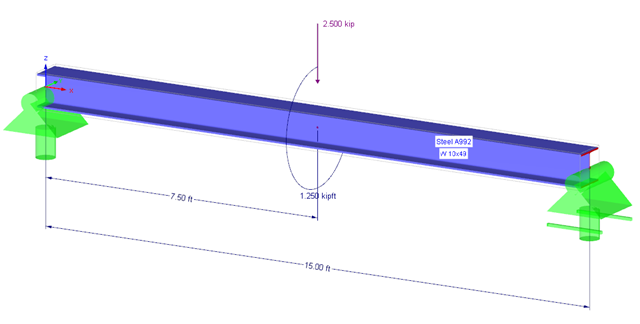
Anhand eines Verifikationsbeispiels soll die Bemessung eines torsionsbeanspruchten Trägers nach AISC Design Guide 9 gezeigt werden. Die Bemessung erfolgt mit dem Zusatzmodul RF-STAHL AISC und der Modulerweiterung RF-STAHL Wölbkrafttorsion mit sieben Freiheitsgraden.

Osłony przeciwwiatrowe to specjalne konstrukcje tekstylne, które mają za zadanie chronić środowisko przed szkodliwymi cząsteczkami chemicznymi, jak również ograniczać erozję wietrzną, przyczyniając się do ochrony cennych zasobów. RFEM i RWIND są używane do analizy konstrukcji wiatrowej dla jednostronnej interakcji płyn-konstrukcja (FSI).
W tym artykule pokazano, jak wymiarować osłony przeciwwiatrowe przy użyciu programów RFEM i RWIND.
W tym artykule pokazano, jak wymiarować osłony przeciwwiatrowe przy użyciu programów RFEM i RWIND.

Analiza modalna jest punktem wyjścia do analizy dynamicznej układów konstrukcyjnych. Można ją wykorzystać do określenia wartości drgań własnych, takich jak częstotliwości drgań własnych, kształty drgań własnych, masy modalne i efektywne współczynniki masy modalnej. Wynik ten może zostać wykorzystany do obliczeń drgań oraz do dalszych analiz dynamicznych (na przykład obciążenia widmem odpowiedzi).
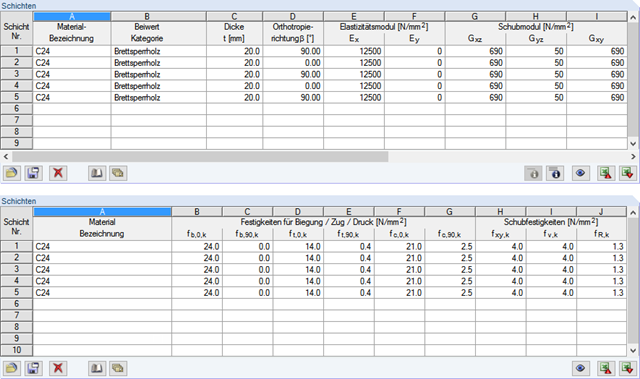
W module dodatkowym RF-LAMINATE można wymiarować elementy konstrukcyjne wykonane z drewna klejonego krzyżowo. Since the design is a pure elastic stress analysis, it is necessary to additionally consider the stability issues (flexural buckling and lateral-torsional buckling).

Sprawdzenie stateczności dla wymiarowania prętów zastępczych zgodnie z EN 1993-1-1, AISC 360, CSA S16 i innymi normami międzynarodowymi wymaga uwzględnienia długości obliczeniowej (tj. efektywnej długości prętów). W programie RFEM 6 długość efektywną można określić ręcznie, przypisując podpory węzłowe i współczynniki długości efektywnej lub, z drugiej strony, poprzez import z analizy stateczności. Obie opcje zostaną przedstawione w tym artykule poprzez określenie efektywnej długości słupa obramowanego na rysunku 1.
Obciążenia eksplozją od materiałów wybuchowych o dużej energii, przypadkowe lub celowe, są rzadkie, ale mogą być wymogiem projektowym. Obciążenia dynamiczne tego typu różnią się od normalnych obciążeń statycznych – są to obciążenia o znacznej wartości, ale oddziałujące bardzo krótkotrwale. Scenariusz eksplozji można przeprowadzić bezpośrednio w programie MES jako analizę historii czasowej, aby zminimalizować utratę żywotności i ocenić różne poziomy uszkodzeń konstrukcji.
Artykuł Wyboczenie giętno-skrętne w konstrukcji drewnianej | Teoria wyjaśnia teoretyczne podstawy analitycznego określania momentu krytycznego M crit lub krytycznego naprężenia zginającego σcrit dla wyboczenia giętno-skrętnego belki zginanej. W poniższym artykule przedstawiono przykłady obliczeniowe, których celem jest weryfikacja wyników analizy wartości własnych względem wyników analitycznych.
Mit dem Zusatzmodul RF-/HOLZ Pro ist es möglich, für die Bemessung nach EN 1995-1-1 den aus der DIN 1052 bekannten Schwingungsnachweis zu führen. Dieser besagt, dass unter ständiger und quasi-ständiger Einwirkung die Durchbiegung am ideellen Einfeldträger einen Grenzwert (nach DIN 1052 6 mm) nicht überschreiten darf. Wenn man den Zusammenhang zwischen Eigenfrequenz und Durchbiegung für einen mit konstanter Streckenlast belasteten, gelenkigen Einfeldträger berücksichtigt, so resultiert aus den 6 mm eine Mindesteigenfrequenz von zirka 7,2 Hz.
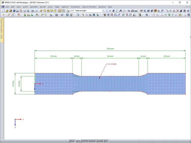
Deformacje sprężyste elementu konstrukcyjnego pod wpływem obciążenia są oparte na prawie Hooke'a, opisującym liniową zależność naprężenie-odkształcenie. Są one odwracalne: po odciążeniu element powraca do swojego pierwotnego kształtu. Jednakże deformacje plastyczne są nieodwracalne i zazwyczaj znacznie większe niż odkształcenia sprężyste. W przypadku naprężeń plastycznych materiałów ciągliwych, takich jak stal, efekty plastyczności występują w miejscach, w których wzrostowi odkształceń towarzyszy zjawisko lokalnego wzmocnienia. Prowadzi to do powstania trwałych deformacji, a w ekstremalnych przypadkach do zniszczenia elementu konstrukcyjnego.
![Belka rozwidlona z rozproszonym obciążeniem (Źródło: [3])](/pl/webimage/009690/467522/01-de-png.png?mw=640&hash=52805a227240ecddbd69b1d113348bf2749c3f9e)
Belki z drewna klejonego o dużej rozpiętości są zazwyczaj podparte na słupie żelbetowym z ograniczeniami skrętnymi.
.png?mw=640&hash=bfebd5ea2d4f77a817fa987424a23a799b3fe711)
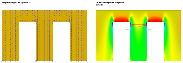
W przypadku smukłych belek zginających o dużym stosunku h/w, obciążonych w kierunku słabej osi bezwładności, występują problemy ze statecznością. Wynika to z ugięcia pasu ściskanego.